
User's Manual
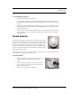
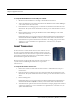
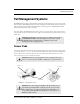
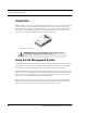
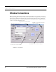
Table Of Contents
- Federal Communication Commission (FCC) Compliance
- Industry Canada Compliance
- Overview
- Intended Audience
- Additional Detailed Documentation
- Contact Information
- Product Warranty
- Chapter 1
- Introduction
- Central Server and Client Computers
- 9450 System
- Exit Alarm Controller
- Card Reader Access Device
- The Exit Alarm Zone
- Exit Alarm Receiver
- Magnetic Reed Switch
- CodeLock Electromagnetic Lock
- Alarming Band Receivers
- Alarming Band Zone
- Quick Look Display
- Transmitters
- Wander Management Transmitter
- Alarming Band Transmitters
- Mother Transmitter
- 9600 QR System
- Gateway
- Router
- Universal Transceiver
- Pendant Transceivers
- Pull-Cords
- Check-in Pull Cord
- Nurse Call
- Smoke Detector
- Asset Transceiver
- Door/Window Transceivers
- Reset Button
- Fall Management Systems
- Sensor Pads
- Using the Fall Management System
- Pagers and Walkie-Talkies
- Event Paging
- Pager Delays, Retries and Escalation
- Walkie-Talkie System
- Chapter 2
- Introductions
- Start the Software
- Window Conventions
- Touchscreen Monitor
- Map Orientation
- Ruleset for Displaying Patient Name
- The Main Window
- The Menu Bar
- Monitor
- Tools
- Paging
- Asset
- Help
- Top Toolbar
- Bottom Toolbar
- Low Battery Icon
- Chapter 3
- Introduction
- Commonly Used Terms
- Login and Passwords
- Units
- Supervised Transmitters
- Global Lockdown
- Common Operations
- Admit
- Patient Admit Information Window
- Asset Admit Information Window
- Discharge
- Escort
- Transfer
- Adjust
- Reports
- Silence
- Chapter 4
- Introduction
- Events
- Devices Displayed on the Map
- Devices Assigned to a Room
- Event Types
- Event Information Window
- Event Information Window Properties
- Red Alarms
- Door Alarm
- Exit Alarm (Wide Gap)
- Smoke Alarm
- Perimeter Alarm
- Cut Band Alarm
- Mismatch Alarm
- Match Alarm
- Link Alarm
- Check Alarm
- Check Transmitter Alarm
- Assistance Required
- Server Missing
- Yellow Alarms
- Client Missing
- Device Fault
- Low Battery
- Blue Alarms
- Door Alarm
- Cut Band Alarm
- Check Transmitter Alarm
- White and Light Blue Alarms
- Auto-enroll (White Alarm only)
- Escort to Expire
- Escort Expired
- Transfer to Expire
- Transfer Expired
- Discharge Expired
- Adjust Expired (White Alarm only)
- Begin Adjust (White Alarm only)
- Admit Complete
- Discharge Complete
- Escort Complete
- Transfer Complete
- Adjust Compete (White Alarm only)
- Chapter 5
- Introduction
- Reports
- Viewing a Report
- Reports Toolbar
- System Reports
- Response Time
- Activities Report
- Alarm Report
- Alarm Response Report
- All Activities Report
- JCAHO Report
- JCAHO Assistance Report
- Alarm Activities Report
- Census Report
- Auto Enrolled History Report
- Adjusted Bands Report
- Transfer Report
- Escort Report
- Discharge Report
- Staff Drill Report
- System Maintenance Report
- Low Batteries Report
- Device Fault Report
- Device Hardware Report
- Transmitter Report
- Users Report
- Training Report
- User Training Report
- All Other Reasons Report
- Links Report
- Links Activities Report
- Patient Reports
- Review Info Report
- Review Activity Report
- Review Response Report
- Asset Reports
- Asset Transmitter Report
- Asset Activities Report

Series 5.0 Software (0510-1059-A_DRAFT) - User Guide 17
9600 QR System
To set up the Nurse Call for use
1. Activate the Nurse Call by pressing the button.
If the Nurse Call is working properly, an Assistance Required alarm event will be listed on the Event
List at the Central Server. The system senses the Nurse Call when it goes into alarm and adds it to its list
of devices.
2. Reset the Nurse Call by pulling the button back to the UP position. The alarm event will automatically
clear from the Event List at the Central Server. If Enforced JCAHO is enabled, you must clear the
alarm at the Central Server.
3. At the Central Server, update the Nurse Call information, for example, giving the Nurse Call a name
and/or assigning it to a room or unit. Refer to the “Update Devices” section in the Series 5.0 Software
Administrator Guide.
Smoke Detector
If your facility is using wireless Smoke Detectors in conjunction with your Series
5.0 Software, a Smoke alarm event is reported in the Event List each time a Smoke
Detector is activated. A Smoke Detector is supervised; a routine signal is sent from
the device and if the signal is not received by the system, a Device Fault event is
generated in the Event List. Smoke Detectors are available from RF Technologies,
Inc.; refer to the manufacturer’s instructions for information regarding mounting,
inserting the batteries, and testing.
The Smoke Detector is powered by a 3V battery with a 3 to 5-year life, based on use. Following these instruction
to insert the battery and set up the Smoke Detector for use.
To insert the battery
1. With the Smoke Detector facing you, remove the detector body
from its mounting base by twisting the detector counter
clockwise.
2. Insert two AA half-size batteries into the battery holder as shown.
Be sure to align the positive (+) end of the battery as marked on
the batteries and battery holder.
3. Replace the detector back onto its mounting base.