
User Manual
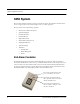
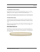
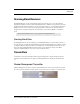
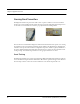
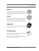
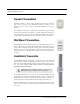
Table Of Contents
- Federal Communication Commission (FCC) Compliance
- Industry Canada Compliance
- Overview
- 9450 System
- Quick Response (QR) System
- Integrated Care Management (ICM) System
- Intended Audience
- Additional Detailed Documentation
- Contact Information
- Product Warranty
- Chapter 1
- Introduction
- Central Server and Client Computers
- Quick Look Display
- 9450 System
- Exit Alarm Controller
- Card Reader Access Device
- The Exit Alarm Zone
- Exit Alarm Receiver
- Magnetic Reed Switch
- CodeLock Electromagnetic Lock
- Alarming Band Receivers
- Alarming Band Zone
- Transmitters
- Wander Management Transmitter
- Alarming Band Transmitters
- Mother Transmitter
- Quick Response System
- Wireless Receiver
- Repeater
- Locator
- Paging Base
- Back-Up Interface
- Pendant Transmitters
- CodeWatch Transmitter
- Pull-Cords
- Check-in Pull Cord
- Smoke Detector
- PIR Sensor
- Door/Window
- Universal Transmitter
- Code Alert ICM System
- Gateway
- Router
- Transceivers
- Pull-Cords
- Nurse Call
- Door/Window Transceivers
- Smoke Detector
- PIR Sensor
- Universal Transceiver
- Pendant Transceivers
- Asset Transceiver
- Fall Management System
- Fall Management System Control Unit
- Fall Management System Sensor Pad
- Advanced 3-Way Care Solution
- Advanced 3-Way Control Unit
- Advanced 3-Way Care Sensor Pads
- Motion Sensor Pad
- Incontinence Sensor Pad
- Messaging Services
- Event Messaging
- Messaging Delays, Retries and Escalation
- Walkie-Talkie System
- Chapter 2
- Introduction
- Start the Software
- Window Conventions
- Touchscreen Monitor
- Quick Reference Tutorial
- Map Orientation
- Ruleset for Displaying Patient Name
- The Main Window
- The Menu Bar
- Monitor
- Tools
- Messaging
- Asset
- Help
- Top Toolbar
- Bottom Toolbar
- Low Battery Icon
- Chapter 3
- Introduction
- Commonly Used Terms
- Login and Passwords
- Units
- Device Supervision
- Global Lockdown
- Common Operations
- Admit
- Admit Information Windows
- Patient Admit Information Window
- Asset Admit Information Window
- Admit Information Tabs
- Patient Main Information Tab
- Discharge
- Escort
- Transfer
- Adjust
- Silence
- Chapter 4
- Introduction
- Events
- Devices Displayed on the Map
- Devices Assigned to a Room
- Event Types
- Event Information Window
- Event Information Window Properties
- Red Alarms
- Door Alarm
- Exit Alarm (Wide Gap)
- Smoke Alarm
- Perimeter Alarm
- Cut Band Alarm
- Mismatch Alarm
- Match Alarm
- Link Alarm
- Check Alarm (not “Check Transmitter Alarm”)
- Check Transmitter Alarm
- Assistance Required
- Fall Alarm
- Wet Alarm
- Turn Alarm
- Server Missing
- Yellow Alarms
- Client Missing
- Low Battery
- Device Fault
- White Alarms
- Auto-enroll
- Admit Complete
- Discharge Expired
- Discharge Complete
- Escort to Expire
- Escort Expired
- Escort Complete
- Transfer to Expire
- Transfer Expired
- Transfer Complete
- Begin Adjust
- Adjust Expired
- Adjust Compete
- Blue Alarms
- Door Alarm
- Cut Band Alarm
- Check Transmitter Alarm
- Light Blue Alarms
- Admit Complete
- Discharge Expired
- Discharge Complete
- Escort to Expire
- Escort Expired
- Escort Complete
- Transfer to Expire
- Transfer Expired
- Transfer Complete
- Adjust Expired
- Adjust Complete
- Chapter 5
- Introduction
- Reports
- Report Buttons
- Sort By Headings
- Additional JCAHO Report Buttons
- System Reports
- Daily Alarms and Activities (Tracer Level 2)
- Alarm Report
- Alarm Activities Report
- Alarm Response Report
- Care Time Report (ICM only)
- Activities Report
- All Activities Report
- All Other Reasons Report
- Facility Trends (Tracer Level 3)
- JCAHO Alarm Trend Report
- JCAHO Assistance Trend Report
- Response Time Trend Report
- Staff Reports (Tracer Level 4)
- Users Report
- User Training Report
- Staff Care Time Report
- Staff Drill Report
- Training Report
- Facility Maintenance (Tracer level 5)
- System Maintenance Report
- Low Batteries Report
- Device Fault Report
- Additional Reports
- Census Report
- Auto Enrolled History Report
- Adjusted Bands Report
- Transfer Report
- Escort Report
- Discharge Report
- Device Hardware Report
- Transmitter Report
- Links Report
- Links Activities Report
- Sensatec Report
- Patient Reports
- Review Info Report
- Review Activity Report
- Review Response Report
- Review Response Reason
- Review Response Reason Detail Report
- Asset Reports
- Asset Transmitter Report
- Asset Activities Report

Series 6.0 Software (0510-1065-A) - User Guide 5
Chapter 1
Equipment Overview
Introduction
This chapter provides equipment overviews of the devices supported by the system and device supervision. The
supervision feature applies to many devices such as the alarming band transmitters, Pendants, Fall Monitoring
and Incontinence devices. A supervised device is the system’s way of ensuring that devices are communicating
properly and within range of the receivers. This chapter also provides details of the Central Server and Client
computers used to run the software as well as Messaging and Walkie-Talkie information.
Central Server and Client Computers
The Central Server is a Windows based computer that runs the software. It
contains the database and provides communication with devices in the
system as well as the Client computer(s).
Depending on your configuration, the system can include several Client
computers. The Client computers allow the user to perform such functions
as admitting, discharging, and authorizing transfers and escorts. Each Client
computer includes a touchscreen monitor that displays alarms as they occur
on a floor plan of the facility.
The Central Server can be located in any area such as the nurse’s central
station or security office. It must be located near a dedicated analog phone
line or broadband connection to allow for remote Technical Support access
when requested by the customer. Each Client computer must be located in a
secure area that can be accessed by staff to enter and retrieve information.
Quick Look Display
The Quick Look Display shows information from the system at remote locations such as a
secondary nurse’s station. When a Red alarm is issued from the system, it is received through
the Quick Look Interface. The type of alarm (Cut Band, Door, Check), location of the alarm
and the transmitter ID are displayed on a large, easy-to-read 2 x 20 Character Vacuum
Fluorescent Displays (VFDs). As new alarms occur, they appear immediately; the display then
begins scrolling through each active alarm. For more information about the Quick Look
Display, see the Quick Look Display and Interface Installation Guide.