
Owner`s manual


7
INSTALLATION (Cont.)
Standard control panel dimensions
Mounting
holes (4)
Control Panel Dimensions
ABCD
Piezo Lit Manual
Series
9-
3
/
4
"5-
3
/
8
"8-
1
/
2
"8-
5
/
8
"
01 Series
5-
1
/
2
"5-
3
/
8
"8-
1
/
2
"7-
3
/
8
"
05 Series
7-
7
/
8
"5-
3
/
8
"8-
1
/
2
"6-
7
/
8
"
Fig. 7-3
D
C
B
A
Table 1
Fig. 7-1
10 sq. in. (min.)
vent opening
2 required
8"
min
12"
min
Recommended Installation
Specifi cations (nominal)
Burner pan assy
Flex
connector
(to valve)
Flex
connector
(from valve)
Control
panel
assy
Fig. 7-2
Top view
The maximum distance from the
center of the burner pan, to the
outer wall, is 30".
18
3
/
8
"
18 3
/
8
"
30"
max
3 - 5"
min
Sub-plate
Center hole
for burner
Mounting holes (4)
28"
dia.
Allow for draining
by drillling 4 holes
across sub-plate
(max. 1/8" in dia.)
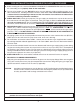
INSTALLATION SPECIFICATIONS
When installing in your enclosure, allow a minimum of 8" (vertical) from the bottom of the control panel to the
burner pan (Fig. 7-1), and set the center of the burner pan no more than 30" from the outer wall (see Fig. 7-1
and 7-2). This will allow adequate access for maintenance and troubleshooting.
Note: Two vent openings for adequate combustion air must be provided (
Fig. 7-1).
FOR 05 SERIES MODELS; the control panel assembly must be within reach of a 110V GFI receptacle
(for the power supply).
05 series
burners
require a
110V GFI
receptacle
Power Supply
(05 series only)
Gas supply
Control Panel Dimensions
ABCD
Piezo Lit Manual
Series
9-
3
/
4
"5-
3
/
8
"8-
1
/
2
"8-
5
/
8
"
05 Series
7-
7
/
8
"5-
3
/
8
"8-
1
/
2
"6-
7
/
8
"
Table 1