
Operating instructions

4
the covered area. Installation in fully-enclosed patio
areas is not recommended.
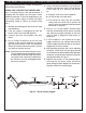
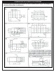
GAS SUPPLY PLUMBING REQUIREMENTS
Do not use a rubber hose within the enclosure
for the barbecue unit. Make sure to tighten every
joint securely.
The gas supply should enter from the rear wall of
the enclosure behind the barbecue unit, at least 2"
(5.1 cm) from either side, and between 2" (5.1 cm)
and 8" (20.3 cm) above the fl oor, as illustrated by
the shaded area in
Fig. 4-2.
If it is not possible to stub the gas line in from the
back of the enclosure, the connection may be made
through the fl oor at the rear of the enclosure. Install
the gas line stub at least 2" (5.1 cm) away from the
side and back walls, but within 6" (15.2 cm) of the
back wall, as illustrated by the shaded area in Fig.
4-2.
Note: An external valve in the gas line is
necessary for safety when your barbecue
is not in use. It also provides for convenient
maintenance and repair. A removable
key is recommended in households with
children.
GAS SUPPLY AND MANIFOLD PRESSURES:
Natural gas - Normal 7" (17.8 cm) water column
(w.c), minimum 3
1
/
2
" (8.9 cm), maximum 10-
1
/
2
"
(26.7 cm).
Propane gas - Normal 11" (27.9 cm) w.c., minimum
8" (20.3 cm), maximum 13" (33 cm).
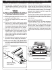
PLANNING FOR INSTALLATION OF YOUR DELUXE SERIES BARBECUE
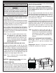
Fig. 4-1 - Ventilation diagram
With our insulating liner you can safely install your
Fire Magic barbecue in wood cabinetry or other
combustible enclosure.
Do not install this unit under unprotected fl ammable
surfaces. Do not install or use this appliance inside
a building, garage, or any other covered area,
including recreational vehicles or boats.
This is a slide-in type unit designed to fi t into open-
front enclosures. The front panel (face) of the unit
is removable for gas hookup, servicing, and burner
adjustment. The face must therefore be removable
after you install the unit.
Note: This unit must be installed so that it can
be removed at a later date if service
is required. Any protrusion into the
barbecue enclosure may obstruct the
frame and prevent the unit from sliding
into place (see GAS SUPPLY PLUMBING
REQUIREMENTS).
COMBUSTION AND COOLING AIR FLOW
You must maintain proper air fl ow for your Fire
Magic barbecue to perform as it was designed (Fig.
4-1). If airfl ow is blocked, overheating and poor
combustion will result. Make sure not to block the
1" (2.54 cm) front air inlet along the bottom of the
barbecue face or the air vent openings along the
outside-left and right edges of the frame.
Note: The 1" (2.54 cm) front air space allows
access to the drip tray.
CAUTION: Keep electrical supply cords away
from all heated surfaces.
EXHAUST REMOVAL
If installed under a patio roof, the grill area should
be fully covered by a chimney and exhaust hood.
An exhaust fan with a rating of 1000 CFM (472 liters
per second) of more may be necessary to effi ciently
remove smoke and other cooking by-products from
Built-in models must be installed in masonry or
other type of fi reproof enclosure. The unit is not
insulated, and therefore must be installed with
18" (45.7 cm) of side and back clearance from
unprotected combustible materials such as wood,
plastic, or stucco with wood framing.
WHERE TO INSTALL YOUR BARBECUE
Fire Magic barbecues are designed for outdoor use only.
Fig. 4-2- Gas stub diagram
4"
2"
24 3/4"
20 3/4"
6"
12"
17 3/4"
WARNING
REV 1 - 0609201134
L-C2-24206