
Owner`s manual


17
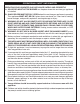
BURNER INSTALLATION (cont.)
REFER TO THE BURNER PARTS LIST WHEN FOLLOWING
THESE INSTRUCTIONS.
1. MAKE SURE THE FIREPLACE GAS SUPPLY IS
TURNED OFF.
2. Locate the gas-supply stub inside the fi replace and
remove the cap, if attached (reference Fig. 17-1).
CAUTION: When removing the cap, make sure the stub does
not turn, loosening the connection inside the wall.
3. Attach the nut end of the fl ex connector to the adapter
found on the valve or, if attached, on the regulator behind
the valve. Tighten securely.
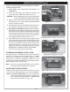
4. Place the burner system in the fi replace. Center the burner
in the fi replace. (Reference Fig. 17-2 for orientation.)
5. Be sure gas to the fi replace is off. Remove the adapter
that is loosely connected to the fl ex connector (coming off
of the burner system). Attach the adapter to the gas-supply
stub using a pipe compound resistant to all gasses. Tighten
securely. Then attach the open end of the fl ex connector
to the adapter. Tighten securely. (See Fig. 17-1.)
6. LEAK TEST: Turn on the fi replace gas supply, and test
at all connections for leaks using the appropriate soapy
water solution. If bubbles appear, a leak is present. Turn
off the gas and tighten at all connections. Repeat until
no leaks are present. If a leak persists, turn off the gas
supply and contact the local gas company or dealer.
NEVER USE A FLAME TO CHECK FOR LEAKS.
Turn off the gas supply prior to proceeding.
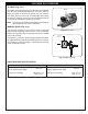
ATTACHING THE BURNER TO THE FLOOR
Two security holes are provided on the base of the burner
assembly for securing it to the fi replace fl oor in a mobile
home, or if the installation or inspector require it in other
circumstances. Using the appropriate hardware for your
fi replace construction (not included); secure the burner system
into the fi replace fl oor (see Fig. 17-3).
Note: If you have a manufactured fi replace, check with the
manufacturer before drilling holes in the fl oor.
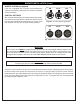
INSTALLING THE DECOR PANEL
Install the decor panel onto the front of the burner (see Fig.
17-4 for 12 valve models and Fig. 17-5 for manual models).
Note: For manual models only; the valve control knob
must be removed in order to place the decor panel.
Then; replace the knob and place the supplied wood
chip in front of the knob (see Fig. 17-5).
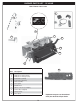
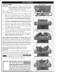
Fig. 17-1 Connect gas supply
Fig. 17-2 Overall orientation (12 valve shown)
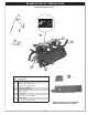
Fig. 17-4 Decor cover installed (12 valve)
Fig. 17-3 Anchoring hole close up
Flex connector
Adapter
Gas supply stub
Fig. 17-5 Decor cover installed (manual valve)