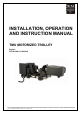
INSTALLATION, OPERATION AND INSTRUCTION MANUAL TMU MOTORIZED TROLLEY English STD-R-KHA-F-CQD-ENG This document and the information contained herein, is the exclusive property of R&M Materials Handling, Inc., and represents a non-public, confidential and proprietary trade secret that may not be reproduced, disclosed to third parties, altered or otherwise employed in any manner whatsoever without the express written consent of R&M Materials Handling, Inc. Copyright © (2009) R&M Materials Handling, Inc.
LM TMU I&M MANUAL/EN/06.15.2009 m m CAUTION: Read the instructions supplied with the product before installation and commissioning. CAUTION: Keep the instructions in a safe place for future reference. Before proceeding with the operation or maintenance of the trolley, it is important that the operating and maintenance personnel read this bulletin carefully in order to ensure the safe and efficient use of the equipment.
LM TMU I&M MANUAL/EN/06.15.2009 FOREWORD This manual has been prepared to acquaint you of the procedures necessary for the installation, operation and maintenance of the equipment you have purchased. Proper use is important to the ultimate performance of this equipment. Careful study of and adherence to the instructions will help ensure safe, dependable operation. It is also recommended that you keep this manual readily accessible to operators as well as maintenance and safety personnel.
LM TMU I&M MANUAL/EN/06.15.2009 m m CAUTION: Read the instructions supplied with the product before installation and commissioning. CAUTION: Keep the instructions in a safe place for future reference. Table of contents 1 2 3 4 5 GENERAL .................................................................................................................................................. 6 1.1 Installation of Trolley...........................................................................................
LM TMU I&M MANUAL/EN/06.15.2009 5.3 Spare Part Replacement .................................................................................................................... 33 5.4 Discarding the Trolley......................................................................................................................... 33 6 SPARE PARTS ........................................................................................................................................ 34 6.1 TMU Trolley ...........
LM TMU I&M MANUAL/EN/06.15.2009 1 y y y y y y y GENERAL Service life of the trolley depends on the way in which it is installed. Any use contrary to our instructions may be dangerous. Before operating the equipment, read and follow the Installation, Operation and Maintenance Instruction manual. Always keep the Instruction manual close to the equipment, readily available to operator and person responsible for maintenance.
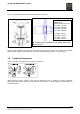
LM TMU I&M MANUAL/EN/06.15.2009 Figure 1. Trolley Installation and Recommended Torque Tensions Recommended Tightening Torque for tension rod nut C1 Trolley: 177 ft-lbs C2 Trolley: 300 ft-lbs C3 Trolley: 545 ft-lbs C5 Trolley: 545 ft-lbs C1 Trolley: 240 N m C2 Trolley: 410 N m C3 Trolley: 740 N m C5 Trolley: 740 N m In all cases, allow minimum of one washer under each tension rod nut. Y + Z = 5/32" [4mm] MAX The total play between wheel flange and the beam flange must not exceed 5/32" [4mm].
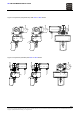
LM TMU I&M MANUAL/EN/06.15.2009 Figure 3. Suspension (Perpendicular) with LM5 or LM10 Hoists Figure 4. Suspension (Parallel) with LM5 or LM10 Hoists 8/38 This document and the information contained herein, is the exclusive property of R&M Materials Handling, Inc.
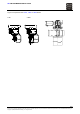
LM TMU I&M MANUAL/EN/06.15.2009 Figure 5. Suspension with LM16, LM20 or LM25 Hoists 1 fall 2 falls 9/38 This document and the information contained herein, is the exclusive property of R&M Materials Handling, Inc., and represents a non-public, confidential and proprietary trade secret that may not be reproduced, disclosed to third parties, altered or otherwise employed in any manner whatsoever without the express written consent of R&M Materials Handling, Inc.
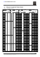
LM TMU I&M MANUAL/EN/06.15.2009 1.3 TROLLEY FLANGE SETTINGS TABLE Table 1. Trolley Flange Settings C1 Trolley C2 Trolley C3 Trolley C5 Trolley Flange Width In [mm] 2.52 [64] 4 0 2 0 0 2.60 [66] 6 2 0 2 0 1 2.83 [72] 14 4 1 8 2 0 16 4 2 10 2 1 18 6 0 10 2 1 3.19 [81] 22 6 2 17 4 1 3.23 [82] 24 8 0 17 4 1 3 0 1 6 1 0 3.50[89] 30 8 3 25 6 1 8 2 0 12 2 0 3.54 [90] 30 10 0 25 6 1 11 2 1 14,5 2 1 3.
LM TMU I&M MANUAL/EN/06.15.2009 10.55 [268] 12 2 2 14 2 2 12 2 11.02 [280] 24 6 0 27 6 1 24 4 0 0 11.34 [288] 32 8 0 35 8 1 32,5 5 1 11.81 [300] 44 10 2 46 10 2 44,5 7 1 11.89 [302] 46 10 3 48 12 0 47 7 2 11.93 [303] 48 12 0 48 12 0 47 7 2 11.97 [304] 460 48 12 0 480 51 12 1 488 48 8 0 12.00 [305] 50 12 1 51 12 1 50,5 8 1 12.05 [306] 50 12 1 51 12 1 50,5 8 1 12.09 [307] 52 12 2 54 12 2 53 8 2 12.
LM TMU I&M MANUAL/EN/06.15.2009 1.4 m y y y y y y y y y y y y Operating Tests – TMU Variable Frequency Drive CAUTION: Always be ready to press the emergency stop button. Check that the electrical connections and mechanical assemblies are all correct. Check that the operating parameters are as required. Check for loose electrical connections. Close the control enclosure cover. Check that the movements of the trolley are free from obstruction and do not cause any danger.
LM TMU I&M MANUAL/EN/06.15.2009 1.5 m y y y y y y y y y y y Operating Tests – TMU Two-speed Motor CAUTION: Always be ready to press the emergency stop button. Check that the electrical connections and mechanical assemblies are all correct. Check that the operating parameters are as required. Check for loose electrical connections. Close the control enclosure cover. Turn on the power supply. Check that the movements of the trolley are free from obstruction and do not cause any danger.
LM TMU I&M MANUAL/EN/06.15.2009 2 TECHNICAL CHARACTERISTICS m 2.1 CAUTION: Never exceed the maximum load capacity that is indicated on the rating plate on the TMU unit. Specification and Minimum Radius Curve – TMU Variable Frequency Drive Table 2. Specification and Minimum Radius Curve - TMU Variable Frequency Drive Trolley Type and Drive C2 + TMU VFD less gear reducer C2 + TMU VFD C3 + TMU VFD Motor Type MF06MK200 Min. Radius Curve 6.56 ft [2m] MF06MK200 MF06MK200 6.56 ft [2m] 6.
LM TMU I&M MANUAL/EN/06.15.2009 2.2 Specification and Minimum Radius Curve – TMU Two-speed Motor Table 3. Specifications and Minimum Radius Curve Trolley Type and Drive C1 + TMU Two-speed Motor Type MF06MK104 Min. Radius Curve 6.56 ft [2m] C2 + TMU Two-speed MF06MK104 6.56 ft [2m] C3 + TMU Two-speed MF06MK104 6.56 ft [2m] C5 + TMU Two-speed MF06MK104 No radius Straight track only ) y y y y y y y y y Note: The trolley control panel is mounted directly to the motor.
LM TMU I&M MANUAL/EN/06.15.2009 3 TMU DRIVE Figure 6. TMU Variable Frequency Drive and TMU Two-Speed Motor 1 2 10 1 4 7 2 3 4 5 3 5 6 8 10 6 7 9 8 9 Table 4. Parts List for TMU Variable Frequency Drive and TMU Two-Speed Motor TMU Variable Frequency Drive 1. Gear/motor unit 6. Brake cover 2. Compact Brake 7. Control enclosure 3. Brake disc 8. Variable frequency drive 4. Sleeve 9. Electrical cable 5. Nut 10. Mounting screw * TMU Two-speed Motor 1. Gear/motor unit 6. Control enclosure 2.
LM TMU I&M MANUAL/EN/06.15.2009 3.1 Motor The motor insulation is class F and the degree of protection is IP55. 3.2 Description of the Gear Reducer 3.2.1 TMU VFD Gear Reducer A single reduction gear reducer is used together with the 100/120 Hz inverter motor. Generally, this gear motor reducer is used when the capacity of the hoist is greater than 1 ton [1000 kg]. The output pinion is cut into the output shaft of the gearbox. Gears are lubricated with semi-fluid grease.
LM TMU I&M MANUAL/EN/06.15.2009 3.4 Mounting Position of Drive Unit Figure 7. Positioning of the TMU Drive Unit The TMU drive unit is to be positioned so that the control enclosure is located to the side of the motor, with the power cable outlet pointing down as shown above. Other mounting positions of the drive are not recommended because they reduce the cooling effectiveness and may cause overheating of the controls. 3.
LM TMU I&M MANUAL/EN/06.15.2009 3.8 y y y y y y Adjustment of Compact Brake Air Gap Disconnect power and lockout disconnecting means on the crane/hoist. Disconnect the power cable plug from the hoist. Remove brake and motor leads from enclosure. Remove the brake cover. Push the brake disk and measure the air gap between the adjustment nut and aluminum ring. The air gap must be 0.008 – 0.012 inches [0.2 - 0.3 mm]. Turn the adjustment nut, to adjust the air gap.
LM TMU I&M MANUAL/EN/06.15.2009 3.10 Trouble Shooting – Brake 3.10.1 Compact Brake The Compact brake is used on the MF06 inverter motor only. Brake will not release: y y y Air gap too large Presence of foreign matter Check Motor Parameter setting ⇒ ⇒ ⇒ adjust air gap clean brake consult Section 4.2.3 ⇒ ⇒ ⇒ ⇒ replace lining replace lining adjust air gap replace lining Insufficient braking torque: y y y y Grease on lining Damaged lining Air gap too large Worn friction material 3.10.2 D.C.
LM TMU I&M MANUAL/EN/06.15.2009 4 TMU VARIABLE FREQUENCY DRIVE 4.1 m Description of the Inverter WARNING: Do not touch any circuit components while the main AC power is on. High voltages are supplied to the inverter (including the programming switches). Wait for at least three minutes after the supply voltage has been switched off before performing any service on the unit. Failure to adhere to this warning can result in injury. Figure 9. Inverter 1. Terminal X1 2. Red LED (fault) 3. Green LED (ok) 4.
LM TMU I&M MANUAL/EN/06.15.2009 4.1.1 Connections The required supply voltage for the inverter is 380v/50Hz to 480v/60Hz. For other available three-phase voltages including 460v, an autotransformer is provided to supply the proper voltage to the inverter. See Section 1.4, Operating Tests, with regards to the verification of the output voltage from the autotransformer to the inverter. Power and control circuit connections are made to X1 terminal as follows: Table 5.
LM TMU I&M MANUAL/EN/06.15.2009 Technical Characteristics Table 6. Technical Characteristics Technical Characteristics Power range Supply voltage* Nominal supply frequency Nominal current Digital control Max output voltage Control voltage range Ambient temperature Humidity Degree of protection Dimensions (W x H x D) Altitude Pollution degree Vibration Shock ) Description 0.75 kW 380 – 480 VAC ±10% 48 – 62 Hz 2.
LM TMU I&M MANUAL/EN/06.15.2009 4.2 m Programming Parameters CAUTION: Do not touch any circuit components while the main AC power is on. High voltages are supplied to the inverter (including the programming switches). Wait for at least three minutes after the supply voltage has been switched off before performing any service on the unit. Failure to adhere to this warning can result in injury.
LM TMU I&M MANUAL/EN/06.15.2009 4.2.1 Speeds and Ramp Time Selections Frequency Output Selection (Set Switches S1 and S2) The minimum and maximum speeds are selected by setting the minimum output frequency and the maximum output frequency. Switch S1 sets the maximum output frequency selection and Switch S2 sets the minimum frequency selection. Table “A” is used for the 35Hz gearless motor and table “B” for the 100Hz motor. Table 8.
LM TMU I&M MANUAL/EN/06.15.2009 Acceleration and Deceleration Ramp Time The acceleration and deceleration ramp times are set using switch S3 as follows: Table 10. Acceleration and Deceleration Ramp Time Switch Settings -1 0 0 0 0 1 1 1 1 1 Switch S3 -2 -3 -4 0 0 0 0 0 1 0 1 0 0 1 1 0 0 1 0 1 1 1 0 0 1 0 1 1 1 0 Acceleration/Deceleration ramp time 2.5 sec (default) 3.5 sec 3.0 sec 5.0 sec 4.0 sec 6.5 sec 4.5 sec 6.0 sec 5.5 sec The default setting for the acceleration and deceleration ramp time is 2.
LM TMU I&M MANUAL/EN/06.15.2009 Two-step Infinitely Variable Speed Control (EP-2) (S4-1 = ON) The TMU VFD features Two-step Infinitely Variable Speed Control and Decelerate to Stop using dynamic braking. Figure 10. TMU VFD Two-Step Infinitely Variable Speed Control and Decelerate Pushbutton position: Rest = decelerate 1.step = maintain speed 2.step = accelerate fwd time pushbutton position speed rev y y y y y S1 input is RUN Forward. Frequency output increases to frequency set by DIP switch S2.
LM TMU I&M MANUAL/EN/06.15.2009 4.3 m Fault Codes and Troubleshooting – TMU VFD WARNING: Do not touch any circuit components while the main AC power is on. High voltages are supplied to the inverter (including the programming switches). Wait for at least three minutes after the supply voltage has been switched off before performing any service on the unit. Failure to adhere to this warning can result in injury. If the TMU VFD malfunctions, a fault lamp blinks on and off.
LM TMU I&M MANUAL/EN/06.15.2009 4.3.1 Troubleshooting Worksheet Table 13.
LM TMU I&M MANUAL/EN/06.15.2009 4.4 Wiring Specification 4.4.1 Wiring Practices – TMU Variable Frequency Drive y y y y y y y y y y y y y Do not connect incoming three-phase AC power to the drive output terminals U, V or W. Do not ground the inverter together with any high-current machines. Before using welders or high-current machines near the crane, disconnect all line and ground wiring. Do not use output contactors between the inverter and the motor.
LM TMU I&M MANUAL/EN/06.15.2009 4.4.2 Wiring Diagram – TMU Variable Frequency Drive 31/38 This document and the information contained herein, is the exclusive property of R&M Materials Handling, Inc., and represents a non-public, confidential and proprietary trade secret that may not be reproduced, disclosed to third parties, altered or otherwise employed in any manner whatsoever without the express written consent of R&M Materials Handling, Inc. Copyright © (2009) R&M Materials Handling, Inc.
LM TMU I&M MANUAL/EN/06.15.2009 4.4.3 Wiring Diagram – TMU Two-speed 32/38 This document and the information contained herein, is the exclusive property of R&M Materials Handling, Inc., and represents a non-public, confidential and proprietary trade secret that may not be reproduced, disclosed to third parties, altered or otherwise employed in any manner whatsoever without the express written consent of R&M Materials Handling, Inc. Copyright © (2009) R&M Materials Handling, Inc. All rights reserved.
LM TMU I&M MANUAL/EN/06.15.2009 5 PREVENTATIVE MAINTENANCE The service life of the TMU depends on the demands placed on it such as the average operating time, and the number of start/stops and its maintenance. 5.1 Maintenance table Table 14. Maintenance Schedule Check Brake operation For loose screws and signs of corrosion Condition of the brake air gap Condition of the drive pinion Measurement of the wheel tread diameter Lubrication of open gear m 5.
LM TMU I&M MANUAL/EN/06.15.2009 6 6.1 SPARE PARTS TMU Trolley 6 3 4 5 22 1 2 1 Fond 15 Fond 14 23 13 25 7 F 9 10 11 24 26 26a 34/38 This document and the information contained herein, is the exclusive property of R&M Materials Handling, Inc., and represents a non-public, confidential and proprietary trade secret that may not be reproduced, disclosed to third parties, altered or otherwise employed in any manner whatsoever without the express written consent of R&M Materials Handling, Inc.
LM TMU I&M MANUAL/EN/06.15.2009 Table 16. TMU Trolley Item 1+3+4+5+6 1+2+4+5+6 7+9+10+11+24 Qty.
LM TMU I&M MANUAL/EN/06.15.2009 6.2 TMU Variable Frequency Drive 6 1 2 3 4 3 2 7 5 Table 17.
LM TMU I&M MANUAL/EN/06.15.2009 6.3 TMU VFD Transformer & Line Reactor 1 Type: 3 PUS800 VA 50- 60 Hz 208- 240- 380- 400- 420440 V 6 7 5 ISO M20 3 2 4 Table 18.
LM TMU I&M MANUAL/EN/06.15.2009 6.4 TMU Two-Speed Motor Table 19.