
User guide


Table Of Contents
RLP I&M MANUAL/EN/07.20.10
10/18
This document and the information contained herein, is the exclusive property of R&M MATERIALS HANDLING, INC. and represents a non-public, confidential and proprietary trade
secret that may not be reproduced, disclosed to third parties, altered or otherwise employed in any manner whatsoever without the express written consent of R&M MATERIALS
HANDLING, INC. . Copyright © (2010) R&M MATERIALS HANDLING, INC. All rights reserved.
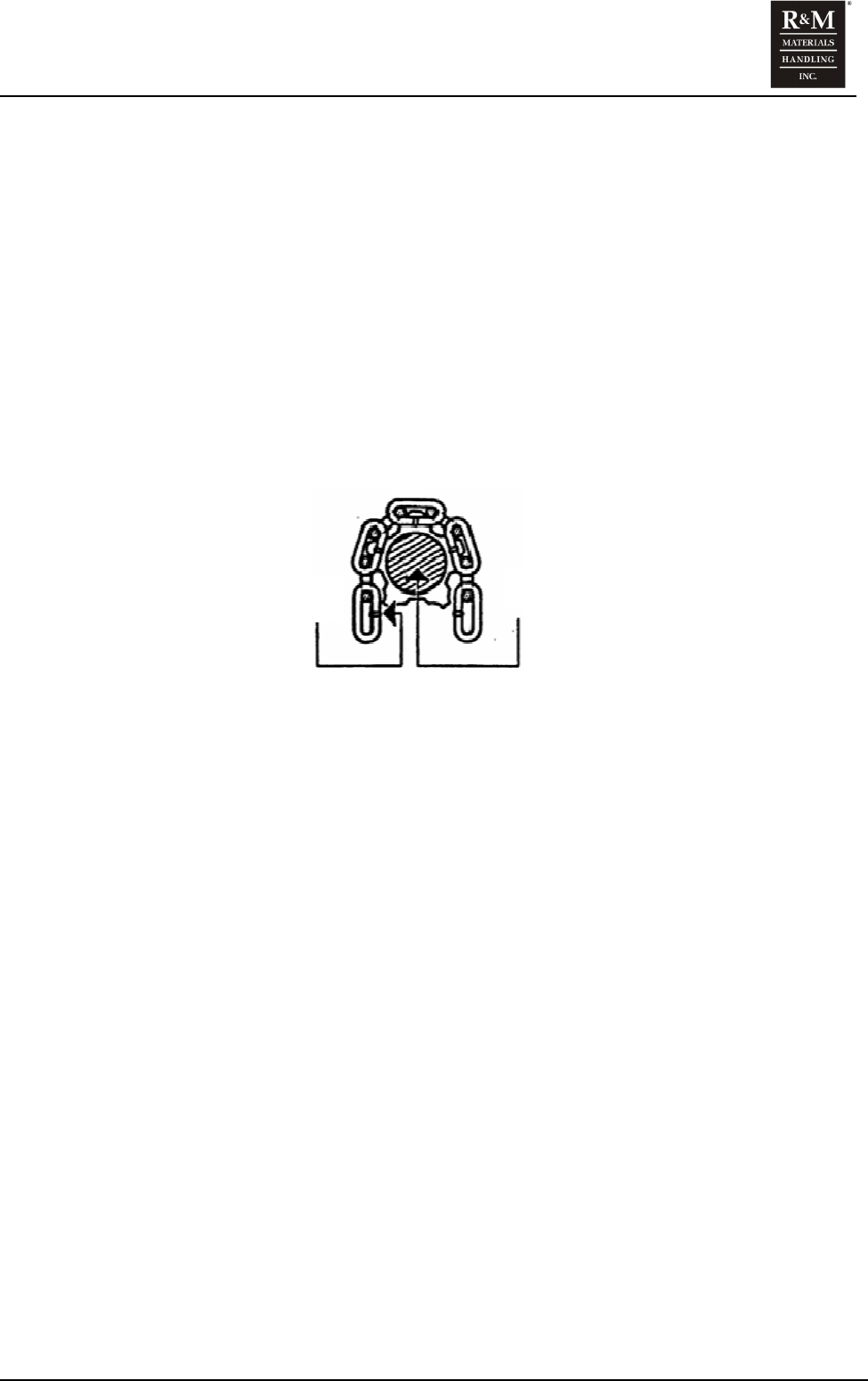
4.1.2 Load Chain Installation
1. Release the control lever.
2. Take a flexible wire of about 20 inches (50 cm) in length and insert it over the lifting head axle
until it comes out on the other side.
3. Hook the chain onto the end of the wire on the load side.
4. Pull the wire to bring the chain in contact with the load wheel while checking the position of the
vertical links. The link weld must be on the inside. (See figure)
5. Regulate the chain tension.
6. Engage the control lever.
7. Adjust the chain.
8. Reinstall the end stop ring.
Figure 2. Link Weld Orientation
Load Wheel
Link Weld