English Original instructions SERVICE MANUAL FOR FREQUENCY CONTROL SYSTEM ControlMaster NXT - - - 092137 12.2011 DOC_SM_TM0400100-0 PS11923 27.7.2012 SUPDOC_SM_TM040-0.ORD 27.7.
R&M Materials Handling, Inc. 4501 Gateway Boulevard Springfield, Ohio 45502 P.: (937) 328-5100 FAX: (937) 325-5319 Table of contents 1 GENERAL INTRODUCTION .............................................................................................................. 4 1.1 Foreword: About This Manual ................................................................................................................. 4 1.2 Symbols Used In This Manual ............................................................
R&M Materials Handling, Inc. 4501 Gateway Boulevard Springfield, Ohio 45502 P.: (937) 328-5100 FAX: (937) 325-5319 6.2 Checks before the first run .................................................................................................................... 37 6.2.1 Power up procedure .......................................................................................................................... 38 6.3 Test run without load ...................................................................
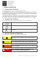
R&M Materials Handling, Inc. 4501 Gateway Boulevard Springfield, Ohio 45502 P.: (937) 328-5100 FAX: (937) 325-5319 1 1.1 GENERAL INTRODUCTION Foreword: About This Manual This manual offers guidance to enable safe and efficient operation of the crane. As a crane operator, taking the time to read this manual will help you to prevent damage to the crane and load, and, most importantly, personnel situated close to the crane. The crane is designed to be safe when used correctly.
R&M Materials Handling, Inc. 4501 Gateway Boulevard Springfield, Ohio 45502 P.: (937) 328-5100 FAX: (937) 325-5319 NOTICE Shall Should 1.4 Addresses situations not related to personal injury, such as likely or possible damage to equipment. Indicates that a rule is mandatory and must be followed. Indicates that a rule is a recommendation, the advisability of which depends on the facts in each situation.
R&M Materials Handling, Inc. 4501 Gateway Boulevard Springfield, Ohio 45502 P.: (937) 328-5100 FAX: (937) 325-5319 1.7 Terminology The following terms and definitions may have been used in this manual: ANSI American National Standards Institute Authorized personnel Persons who are authorized by the owner and who have the necessary training to carry out operation or service actions. CE marking The product’s CE-marking indicates that the product complies with the appropriate CE regulations.
R&M Materials Handling, Inc. 4501 Gateway Boulevard Springfield, Ohio 45502 P.: (937) 328-5100 FAX: (937) 325-5319 1.8 Directives and standards 1.8.1 CE/CSA/UL/CCC This product complies with one or more of the following requirements and directives described in this section. For more detailed information about which requirements the product meets, see the main sticker attached to the device.
R&M Materials Handling, Inc. 4501 Gateway Boulevard Springfield, Ohio 45502 P.: (937) 328-5100 FAX: (937) 325-5319 Second environment is an environment that includes all the establishments other than those directly connected a low-voltage power supply network. EMC levels There are three EMC levels: S, N and 0. S-level: No manufacturer’s EMC solution is adopted and products will be used in other market areas than European Union (EU) when local power supply system is the grounded network.
R&M Materials Handling, Inc. 4501 Gateway Boulevard Springfield, Ohio 45502 P.: (937) 328-5100 FAX: (937) 325-5319 2 2.1 IDENTIFICATION Product identification data This manual covers the installation and use of the switch based frequency converter model. Converter can be used on traveling movement application and chain hoist lifting application. Application type is selected with switch S10-2. Switch settings are explained on section Parameters.
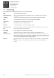
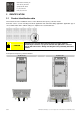
R&M Materials Handling, Inc. 4501 Gateway Boulevard Springfield, Ohio 45502 P.: (937) 328-5100 FAX: (937) 325-5319 2.1.1 Main sticker The main sticker shows, for example, the model and serial number of the frequency converter, as well as the rated voltage. 1 Product model number Indicates the exact model of the product. 2 Identification number A unique string that identifies the unit. 3 Input Indicates the acceptable mains voltage range, current and frequency that the product can be connected to.
R&M Materials Handling, Inc. 4501 Gateway Boulevard Springfield, Ohio 45502 P.: (937) 328-5100 FAX: (937) 325-5319 3 3.1 SAFETY RELATED INSTRUCTIONS Intended use of the frequency converter Travelling movements These frequency converters are designed for industrial crane usage for controlling the speed of travelling motors. Hoisting movements These frequency converters are designed for industrial crane usage for controlling lifting speed in chain hoist applications. 3.
R&M Materials Handling, Inc. 4501 Gateway Boulevard Springfield, Ohio 45502 P.: (937) 328-5100 FAX: (937) 325-5319 4 4.1 PREPARING THE PRODUCT FOR USE Transport and storage The product shall be stored in an environment meeting the following conditions: storing temperature between -40 and +70 degrees Celsius relative humidity below 95%, no condensation After unpacking the component, ensure that there are no visible signs of transport damage. 4.
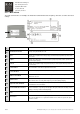
R&M Materials Handling, Inc. 4501 Gateway Boulevard Springfield, Ohio 45502 P.: (937) 328-5100 FAX: (937) 325-5319 4.3 Mounting and installation 4.3.1 Dimensions The main dimensions of the two models of the product are described in the following illustrations. 003 dimensions (mm) 006 dimensions (mm) H1 H2 H3 W1 W2 W3 D1 D2 H1 H2 H3 W1 W2 W3 D1 D2 157 147 137 66 38 4.5 99 7 195 183 170 122 102 6 122 20 4.3.
R&M Materials Handling, Inc. 4501 Gateway Boulevard Springfield, Ohio 45502 P.: (937) 328-5100 FAX: (937) 325-5319 Screw mounting with integrated braking resistor 1 Initially tighten the screws so that they can be fitted in the holes in the upper part of the braking resistor housing. Use screw size: M5 with screw locking liquid. 2 Once the device is held up by the screws, tighten the upper screws and then fit screws in the lower part of the braking resistor housing.
R&M Materials Handling, Inc. 4501 Gateway Boulevard Springfield, Ohio 45502 P.: (937) 328-5100 FAX: (937) 325-5319 Unmounting from the DIN rail 1 Removal of the frequency converter from the DIN rail is done by pressing the releasing latch of the device with a screwdriver. 2 Lift the lower part of the device and remove it from the DIN rail. 4.3.3 Terminals WARNING To avoid an electrical shock, the mains supply shall be disconnected.
R&M Materials Handling, Inc. 4501 Gateway Boulevard Springfield, Ohio 45502 P.: (937) 328-5100 FAX: (937) 325-5319 mm2 AWG 1.5 – 4.0 16 – 12 1.0 – 2.
R&M Materials Handling, Inc. 4501 Gateway Boulevard Springfield, Ohio 45502 P.: (937) 328-5100 FAX: (937) 325-5319 The digital input terminals on both models DANGER THE MOTOR TERMINALS (U, V, W / T1, T2, T3) AND BRAKING RESISTOR TERMINALS (R+ AND R- WHEN APPLICABLE) ARE LIVE WHEN THE FREQUENCY CONVERTER IS CONNECTED TO A MAINS SUPPLY, EVEN WHEN THE MOTOR IS NOT RUNNING.
R&M Materials Handling, Inc. 4501 Gateway Boulevard Springfield, Ohio 45502 P.: (937) 328-5100 FAX: (937) 325-5319 4.3.6 EMC The frequency converter has an internal EMC filter in the power supply. By default, the EMC level of the frequency converter is set to N by the manufacturer. If the mains network is non-grounded (IT-network), the frequency converter’s EMC level shall be changed to 0 by removing the filter capacitor disconnection screw.
R&M Materials Handling, Inc. 4501 Gateway Boulevard Springfield, Ohio 45502 P.: (937) 328-5100 FAX: (937) 325-5319 The bridge travelling motor installed at the opposite end from the bridge panel. The bridge travelling motor installed at the bridge panel end of the main girder. The frequency converter. If the European regulations for EMC are not adhered to, both motor cables can be 40 m long.
R&M Materials Handling, Inc. 4501 Gateway Boulevard Springfield, Ohio 45502 P.: (937) 328-5100 FAX: (937) 325-5319 5 5.1 PARAMETERS Switch settings Settings of the switch model frequency converter are selected with 26 dip switches, which are located at the top of the frequency converter. The switches are divided into groups of 2 or 3 switches. Each switch-group is labelled with positions S1 through S10. An individual switch is given a number. For example, S1-1 denotes the first switch of switch group S1.
R&M Materials Handling, Inc. 4501 Gateway Boulevard Springfield, Ohio 45502 P.: (937) 328-5100 FAX: (937) 325-5319 Note: The switch setting description sections are arranged in the same order as the settings shall be selected. The switch should be turned gently with small screwdriver, moving screwdriver only sideways. NOTICE 21/53 The switch will be damaged if it is twisted or turned using too much force. R&M Materials Handling, Inc.
R&M Materials Handling, Inc. 4501 Gateway Boulevard Springfield, Ohio 45502 P.: (937) 328-5100 FAX: (937) 325-5319 5.2 Switch settings in traveling movement application Converter’s default application is traveling movement application. Application can be changed with switch group S10-2. Switch S10- 2 Chain hoist lifting application 0 The chain hoist lifting application is not active. 1 The chain hoist lifting application is active. In traveling movement application ie.
R&M Materials Handling, Inc. 4501 Gateway Boulevard Springfield, Ohio 45502 P.: (937) 328-5100 FAX: (937) 325-5319 5.2.2 S1 Maximum driving frequency in traveling movement application This switch group adjusts the maximum driving frequency of the motor. The switch settings are shown in the following table. The selected motor nominal frequency (switch group S9) defines which column of the table is used. The maximum driving frequency shall not be set higher than the nominal frequency of the motor.
R&M Materials Handling, Inc. 4501 Gateway Boulevard Springfield, Ohio 45502 P.: (937) 328-5100 FAX: (937) 325-5319 5.2.3 S2 Minimum driving frequency in traveling movement application This switch group adjusts the minimum driving frequency of the motor. The switch settings are shown in the following table. The selected motor nominal frequency defines which part of the table is used.
R&M Materials Handling, Inc. 4501 Gateway Boulevard Springfield, Ohio 45502 P.: (937) 328-5100 FAX: (937) 325-5319 5.2.4 S6 U/f curve settings in traveling movement application The effect of stator resistance at low frequencies is compensated for by increasing the U/f-ratio. The U/f curve settings for the different motors are shown in the following table. Note: • Zero Freq Volt[%] = output voltage at 0 Hz given as a percentage of the voltage at the motor’s nominal frequency.
R&M Materials Handling, Inc. 4501 Gateway Boulevard Springfield, Ohio 45502 P.: (937) 328-5100 FAX: (937) 325-5319 5.2.5 S7 Current Limit in traveling movement application The frequency converter limits the maximum current. The limit settings for different currents are shown in the following table. The limit is a percentage of the device’s nominal current. Switch S7 Frequency converter model Nominal current [A] 003 2.4 006 5.6 Current Limit [%] 003 [A] 006 [A] -1 -2 -3 0 1 0 150 % (*) 3.
R&M Materials Handling, Inc. 4501 Gateway Boulevard Springfield, Ohio 45502 P.: (937) 328-5100 FAX: (937) 325-5319 5.2.6 S8 Number of motors in traveling movement application The model is only used with compact brake motors, which need DC (direct current) to open the brake at the start and to keep the brake open during electrical braking. Depending on the nominal current of the frequency converter, up to four motors can be connected to it.
R&M Materials Handling, Inc. 4501 Gateway Boulevard Springfield, Ohio 45502 P.: (937) 328-5100 FAX: (937) 325-5319 5.2.7 S3 Acceleration and deceleration ramp times in traveling movement application This switch group adjusts the ramp time for motor acceleration and deceleration. The ramp time is defined as from zero to the set maximum frequency. The acceleration and deceleration times are the same. Contact the product’s manufacturer, if it is necessary to recalculate the ramp time.
R&M Materials Handling, Inc. 4501 Gateway Boulevard Springfield, Ohio 45502 P.: (937) 328-5100 FAX: (937) 325-5319 5.2.8 S4 Control method and slowdown mode in traveling movement application The frequency converter can be parametrised for two different control methods. The control method options are listed in the following table. The descriptions of the control methods are given in the section “Control methods”.
R&M Materials Handling, Inc. 4501 Gateway Boulevard Springfield, Ohio 45502 P.: (937) 328-5100 FAX: (937) 325-5319 Switch S4 - 2 Slowdown mode Operation 0 Direction memory on When the power is turned off, the limit switch status is saved. When power is turned back on and limit switch circuit is opened, driving is allowed with maximum speed in the opposite direction.
R&M Materials Handling, Inc. 4501 Gateway Boulevard Springfield, Ohio 45502 P.: (937) 328-5100 FAX: (937) 325-5319 5.2.9 S5 Limit operations in traveling movement application The functions of the slowdown limit input DI4, stop limit input DI5 and slowdown limit frequency are adjusted with this switch group. Value of the slowdown speed is given as a percentage of the set maximum frequency (see section “S1 Maximum driving frequency”).
R&M Materials Handling, Inc. 4501 Gateway Boulevard Springfield, Ohio 45502 P.: (937) 328-5100 FAX: (937) 325-5319 5.2.10 S10 Terminal DI6 operation in traveling movement application Input DI6 is used for external faults as motor thermal protection. The function of the DI6 input can be changed according to the following table. The NTC thermistor can be used with external thermistor relay. CAUTION Wrong parameter setting may accidentally deactivate the DI6 input, possibly causing hazardous situations.
R&M Materials Handling, Inc. 4501 Gateway Boulevard Springfield, Ohio 45502 P.: (937) 328-5100 FAX: (937) 325-5319 5.3 Switch settings on chain hoist lifting application The chain hoist lifting application is activated with switch group S10. The switches must be set according to the descriptions in the following section. 5.3.1 S10 -2 Chain hoist lifting application The switch S10 – 2 activates the chain hoist lifting application.
R&M Materials Handling, Inc. 4501 Gateway Boulevard Springfield, Ohio 45502 P.: (937) 328-5100 FAX: (937) 325-5319 5.3.3 S7 Current limit on chain hoist lifting application The frequency converter limits the maximum current. The limit settings for different currents are shown in the following table. The settings are applicable to the model 003 only. Switch S7 34/53 Current Limit -1 -2 -3 Current Limit [%] 003 [A] 0 0 0 200 4.8 0 0 1 190 4.6 0 1 0 180 4.3 0 1 1 170 4.
R&M Materials Handling, Inc. 4501 Gateway Boulevard Springfield, Ohio 45502 P.: (937) 328-5100 FAX: (937) 325-5319 5.3.4 S3 Acceleration and deceleration ramp times on chain hoist lifting application Switch group S3 adjusts the ramp time as described in chapter “S3 Acceleration and deceleration ramp times”, but values for acceleration and deceleration differ from normal (travelling application) use. Values for chain hoist lifting are shown in the table below.
R&M Materials Handling, Inc. 4501 Gateway Boulevard Springfield, Ohio 45502 P.: (937) 328-5100 FAX: (937) 325-5319 6 COMMISSIONING If any problems or malfunctions occur during the commissioning, refer to the chapter “Troubleshooting” to find out the reason. The source of any problems with the product must be solved before continuing with the commissioning procedure. 6.
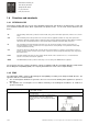
R&M Materials Handling, Inc. 4501 Gateway Boulevard Springfield, Ohio 45502 P.: (937) 328-5100 FAX: (937) 325-5319 6.2 Checks before the first run 1 Check that the main power is switched off. 2 When installing a new unit, disconnect the motor (U / T1, V / T2, W / T3) cables to prevent damage to the frequency converter. Measure the insulation resistance of the motor windings (each phase to ground). Insulation resistance requirement for new motor: Cold motor (10..
R&M Materials Handling, Inc. 4501 Gateway Boulevard Springfield, Ohio 45502 P.: (937) 328-5100 FAX: (937) 325-5319 5 Make sure that the control devices are at the neutral position. 6 Turn the power on (main and control voltage). 7 Measure the power supply voltage. The main voltage shall be between 380-480VAC. 8 Measure the control voltage. The control voltage shall be between 42 and 240 VAC. 6.2.1 Power up procedure 1 Make sure that the main power isolation switch is ON.
R&M Materials Handling, Inc. 4501 Gateway Boulevard Springfield, Ohio 45502 P.: (937) 328-5100 FAX: (937) 325-5319 4 Energize the product by pressing the start pushbutton. 5 The frequency converter goes into a ready-to-run state after the power supply is connected. The frequency converter verifies that both direction signals are switched off. 6 After start up, if a green LED is lit the frequency converter will accept driving commands.
R&M Materials Handling, Inc. 4501 Gateway Boulevard Springfield, Ohio 45502 P.: (937) 328-5100 FAX: (937) 325-5319 2 Check limit switches manually, if possible, by measuring their state when they are turned into different positions. After check turn the limit switches back to neutral position. 3 1. Drive in free direction at minimum speed for 5 to 10 seconds. 2. Accelerate to full speed 3. Run for 5 to 10 seconds with full speed 4. Stop 5. Repeat for the opposite direction.
R&M Materials Handling, Inc. 4501 Gateway Boulevard Springfield, Ohio 45502 P.: (937) 328-5100 FAX: (937) 325-5319 2 Check the deceleration ramp time. Ensure that the motor brake closes after the movement has stopped. If the movements stops suddenly during the deceleration, check the frequency converter fault code. If it is fault 2, increse the ramp time with switch group S3. 3 Check the limit switch functions with full load. If one step slow down limit switch is used: 1.
R&M Materials Handling, Inc. 4501 Gateway Boulevard Springfield, Ohio 45502 P.: (937) 328-5100 FAX: (937) 325-5319 6.5 After the test run Record the parameter value changes in a parameter list. Changed values are needed if the frequency converter will be replaced with a new one. Upon completing the test: Ensure that all of the remarks and parameter values are sent to the manufacturer. Up to date parameter list ensure correct parameter settings in spare part deliveries.
R&M Materials Handling, Inc. 4501 Gateway Boulevard Springfield, Ohio 45502 P.: (937) 328-5100 FAX: (937) 325-5319 7 7.1 OPERATING INSTRUCTIONS Normal function 7.1.1 Control methods EP (Electronic Potentiometer) stepless pushbutton control Released (stop): The device doesn’t move or, if it is already moving, it will decelerate to a complete stop. Fully pressed (accelerate): The device accelerates continuously until the pushbutton is released or the maximum speed is reached.
R&M Materials Handling, Inc. 4501 Gateway Boulevard Springfield, Ohio 45502 P.: (937) 328-5100 FAX: (937) 325-5319 CAUTION When a pushbutton is pressed or released, the movement will accelerate or decelerate smoothly. The operator SHALL account for the starting and stopping distances before making crane movements. MS2 Multistep 2 pushbutton control The motor moves at a speed corresponding to the pushed step of the pushbutton.
R&M Materials Handling, Inc. 4501 Gateway Boulevard Springfield, Ohio 45502 P.: (937) 328-5100 FAX: (937) 325-5319 8 MAINTENANCE Note: Mechanical and electrical maintenance work requires special skills and tools to ensure safe and reliable operation of the product. Maintenance work shall be carried out only by authorized service personnel or an experienced service technician authorized by the product’s manufacturer or manufacturer’s representative.
R&M Materials Handling, Inc. 4501 Gateway Boulevard Springfield, Ohio 45502 P.: (937) 328-5100 FAX: (937) 325-5319 9 TROUBLESHOOTING The purpose of troubleshooting is primarily to determine whether problems are caused by the frequency converter or external devices. It is also possible that a faulty external device has caused damage to the frequency converter. In that case it is very important to repair or change any faulty devices to prevent recurring problems.
R&M Materials Handling, Inc. 4501 Gateway Boulevard Springfield, Ohio 45502 P.: (937) 328-5100 FAX: (937) 325-5319 9.2 Exceptional situations 9.2.1 Determining movement direction The frequency converter needs to know in which direction the motor is running to execute the limit functions properly, because it has only one input for the slowdown limit and one input for the stop limit.
R&M Materials Handling, Inc. 4501 Gateway Boulevard Springfield, Ohio 45502 P.: (937) 328-5100 FAX: (937) 325-5319 X Blink Seven times X OFF 7 Other fault Note: There is a pause after each time the green LED has finished blinking the error code sequence. After the pause, the green LED starts blinking again. The warning and fault code numbers and corresponding warnings and faults, possible causes and suggested solutions are listed in the following table.
R&M Materials Handling, Inc. 4501 Gateway Boulevard Springfield, Ohio 45502 P.
R&M Materials Handling, Inc. 4501 Gateway Boulevard Springfield, Ohio 45502 P.: (937) 328-5100 FAX: (937) 325-5319 10 TAKING PRODUCT OUT OF OPERATION 10.1 Disposal of waste materials Waste material from installation, maintenance or dismantling shall be disposed of according to local regulations. If the product is taken out of use, the metal and electrical parts should be recycled. In addition to local regulations, liquids like oil, grease and other chemicals shall never be spilled onto the ground or soil.
R&M Materials Handling, Inc. 4501 Gateway Boulevard Springfield, Ohio 45502 P.: (937) 328-5100 FAX: (937) 325-5319 11 TECHNICAL DATA Mains connection Supply voltage Uin 380 - 480V, -15%...+10% 3-phase Supply voltage frequency 45…66 Hz Connection to mains Motor connection Once per minute or less (normal case) Output voltage 0 — 0,95*Uin Nominal output current 003: IN 2.4A (max 3.6A), 006: IN 5.6A (max 7.7A) Continuous output current Ambient temperature max. +50ºC, overload 1.
R&M Materials Handling, Inc. 4501 Gateway Boulevard Springfield, Ohio 45502 P.
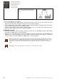
R&M Materials Handling, Inc. 4501 Gateway Boulevard Springfield, Ohio 45502 P.: (937) 328-5100 FAX: (937) 325-5319 13 APPENDIX 1, ELECTRICAL CONNECTIONS Sample electrical drawing for limit switch connections. DI1 Direction 1 DI2 Direction 2 DI3 – DI6 Digital input DCOM Control voltage, neutral STOP Stop limit switch SLOW Slowdown limit switch BI-METAL SWITCH Thermal limit switch NOTICE 53/53 All electrical connections shall do according to valid project specific electrical drawings.