
Service Manual

R&M Materials Handling, Inc.
4501 Gateway Boulevard
Springfield, Ohio 45502
P.: (937) 328-5100
FAX: (937) 325
-
5319
15/53
R&M Materials Handling, Inc. reserves the right to alter or amend the above information without notice.
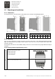
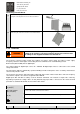
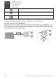
Unmounting from the DIN rail
1
Removal of the frequency converter from the DIN rail is done by
pressing the releasing latch of the device with a screwdriver.
2
Lift the lower part of the device and remove it from the DIN rail.
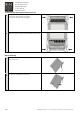
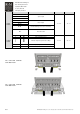
4.3.3 Terminals
WARNING
To avoid an electrical shock, the mains supply shall be disconnected. Before
working on the frequency converter’s terminals, wait at least 5 minutes after
the cooling fan has stopped and LEDs have switched off.
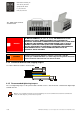
The frequency converter power module has terminals for 3-phase power supply and 3-phase motor supply.
Frequency converters of the higher current rating also have terminals for an external braking resistor.
Both models (003 and 006) have 6 digital inputs.
The control voltage for digital inputs can be 42 – 240VAC. All digital inputs must be connected to same control
voltage transformer.
The transformer shall have galvanically separated windings and the neutral phase of the secondary circuit must be
connected to protective earth.
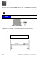
The frequency converter has protection against earth faults in the motor or in the motor cables. Since the frequency
converter has a plastic cover, it does not ground via the DIN rail.
Digital inputs DI1 and DI2 are always used for direction commands. The functions of inputs DI3 – DI6 vary
depending on parameter settings. DI6 is an ES (External Stop) input that is connected to the motor’s thermal
protection as standard. All terminals are listed in the table below.
Power supply terminal
(L1, L2/N, L3)
The mains power cable shall be connected to this terminal.
Motor cable terminal
(U/T1, V/T2, W/T3)
The motor cable shall be connected to this terminal.
Braking resistor terminal
(R+, R-)
The braking resistor wires shall be connected to this terminal (model 006 only).
Grounding wire terminals
The protective grounding conductor shall be connected to these terminals.
Terminal / Name Function Cable size