
Service Manual

R&M Materials Handling, Inc.
4501 Gateway Boulevard
Springfield, Ohio 45502
P.: (937) 328-5100
FAX: (937) 325
-
5319
20/53
R&M Materials Handling, I
nc. reserves the right to alter or amend the above information without notice.
5 PARAMETERS
5.1 Switch settings
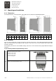
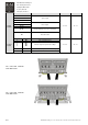
Settings of the switch model frequency converter are selected with 26 dip switches, which are located at the top of
the frequency converter. The switches are divided into groups of 2 or 3 switches. Each switch-group is labelled with
positions S1 through S10.
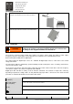
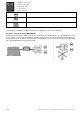
An individual switch is given a number. For example, S1-1 denotes the first switch of switch group S1. The state of
each switch is either 0 (Off) or 1 (On) as shown in the image below. The switch interface is designed so that the
switches need to be altered from 0 as little as possible.
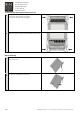
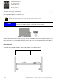
The switch group S9 shall be set first, because the functionality of the switch groups S1 and S2 depend on the
settings of the group S9.
The switch groups are:
S1 Maximum driving frequency
S2 Minimum driving frequency
S3 Acceleration and deceleration ramp times
S4 Control method and slowdown mode
S5 Limit operations
S6 Voltage at low frequencies (U/f curve)
S7 Current limit
S8 Start and stop current
S9 Motor nominal frequency
S10 Terminal DI6 operation
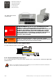
Note: Changes in the switch settings come into effect only after powering down and restarting the frequency converter.
CAUTION
The parameters set by the manufacturer shall not be changed. Changing the
parameters can lead to unexpected functioning of the equipment.