
Service Manual Instruction Manual


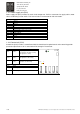

R&M Materials Handling, Inc.
4501 Gateway Boulevard
Springfield, Ohio 45502
P.: (937) 328-5100
FAX: (937) 325
-
5319
15/83
R&M Materials Handling, Inc. reserves the right to alter or amend the above information without notice.
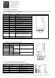
1.12 Signal cabling
1.12.1 Shielded signal cable
It's recommended to use twisted pair and braided shielded signal cables. Foil type shield is not sufficient enough in crane
applications because of poor mechanical durability. Cable insulation material effects to cable capacitance.
Recommended cable capacitance between signal-signal and signal-ground is equal or less than 100pF/m (31pF/ft).
It is not recommended to use shielded flat cable, because its capacitance is extremely high and this may cause high
frequency interference.
1.12.2 Reference signals
Shielded round cables must be used for analog reference signals. The shield is to be grounded only at one end of the
cable.
1.12.3 Sensor bearing
The cable for the sensor bearings must be shielded round cable and grounded 360° at both ends.
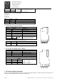
1.12.4 Encoder
The encoder connections may be split into two cables, then the signal conductors (4pcs) should go together in one cable
and the supply and common (+24V/0V) together in another cable. The encoder cable(s) must be shielded round cable(s)
and grounded 360° at both ends.
m Note! All shielded cables must be placed as far from the motor cables as possible
(>20cm). Shielding must be continuous. The "pigtail" (= the end to be connected) of
the shield should not be used, instead 360° groundi ng should be used to minimize
disturbances.
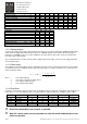
m If control cable length is over 100m (from transformer to inverter) or inverter is not
mounted on the crane, make sure that Basic I/O board (Slot A) is at least revision
271G and I/O Extension board (Slot D) is at least revision 266H
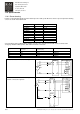
1.13 EMC compatible grounding
1.13.1 Construction connections
All metal construction parts of the cubicle must be electrically connected to each other using largest possible surface
area. Paint to paint connection must not be used.
1.13.2 Cable connections
Control cables and power cables should be separated and routed separately for eliminating noise coupling. The distance
between braking resistor cables and the other cables should be kept as long as possible. The distance between the
resistor cables should be kept as low as possible to prevent the antenna behavior. Cable lengths should be kept as short
as possible to minimize coupling capacitances and inductances.
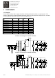
1.13.3 Shielded control cables
Shielded control cables should be grounded in both ends. The shield must be connected to the ground using the largest
possible surface area. Extra intermediary terminators cutting the shield are not allowed, the shield should be as integrity
as possible. Spare conductors should be grounded in the both ends. All shielded cable shields should be 360° grounded.