
Service Manual Instruction Manual


R&M Materials Handling, Inc.
4501 Gateway Boulevard
Springfield, Ohio 45502
P.: (937) 328-5100
FAX: (937) 325
-
5319
19/83
R&M Materials Handling, Inc. reserves the right to alter or amend the above information without notice.
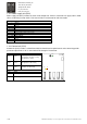
28
ROC1
Relay output, 250V 8A, normal open
29 ROC1
Relay contact ROC1 closes when inverter is powered and no faults occurs
Relay contact ROC1 opens if the SSU has tripped in:
Overspeed
Speed difference
Zero speed
Relay test fault
Watch dog fault
LED Blinking Status
Red 1Hz OK
Yellow 0.25Hz OK
Yellow 4Hz Board internal fault or communication fault with control unit
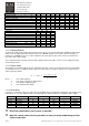
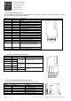
1.14.6 I/O Extension board (Slot D)
NXOPTB9 / I/O Extension board ID: 52305691
YELLOW
1 2 3 4 5 6 7 8
Terminal Signal name Description
1 DID1 Not used
2 DID2 42-240Vac 50/60Hz
3 DID3 42-240Vac 50/60Hz
4 DID4 42-240Vac 50/60Hz
5 DID5 42-240Vac 50/60Hz
6 COM Common for DID1-DID5
7
ROD1
Relay output, 250V 8A, normal open
For fan of braking resistor unit
8 ROD1
The threshold voltage for digital inputs DID1-DID5 is 35VAC.
LED Blinking Status
Yellow 0.25Hz OK
Yellow 4Hz Board internal fault or communication fault with control
unit
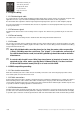
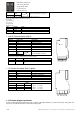
1.14.7 System bus board (Slot E, option)
NXOPTD1L System bus board ID: 52354858
H1 H2 H3 H4
Terminal Signal name Description
H1 RX1 SystemBus optical input 1.
H2 RX2 SystemBus optical input 2.
H3 RX3 SystemBus optical output 1.
H4 RX4 SystemBus optical output 2.
Optical cables
Specification ID:
Length
[m]
Bend radius
SYS-1M 52354911 1 > 35mm ( >1.3 inch)
SYS-2M 52354876 2 > 35mm ( >1.3 inch)
SYS-4M 52354912 4 > 35mm ( >1.3 inch)
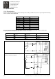
1.15 Control voltage transformer
Power of control voltage transformer has to be n * 50VA + 50VA (min. 250VA), n = number of inverters. This power does
not have to be added to otherwise needed transformer power.