
Service Manual Instruction Manual


R&M Materials Handling, Inc.
4501 Gateway Boulevard
Springfield, Ohio 45502
P.: (937) 328-5100
FAX: (937) 325
-
5319
21/83
R&M Materials Handling, Inc. reserves the right to alter or amend the above information without notice.
m Critical damage if: The supply voltage is over 28V or a short circuit between the
signal and the supply, or induction heating or hammer mounting. In case of sensor
damage, the whole motor has to be changed.
Buffer amplifier must be located as close to the sensor bearing as possible (maximum distance 2.5m)
The cable between the buffer amplifier and inverter must be
- as far as possible from the cables of motor and braking resistor (minimum distance >20cm)
- a shielded and twisted cable
- grounded (the shield) at both ends, 360
°
grounding on inverter terminal
- the shield should be grounded always when going through terminals
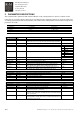
1.16.2 Encoder
Standard encoder has 24 pulses per revolution. It is also allowed to use 600, 1000, 1024, 2000 or 2048 ppr encoders, but
then there has to be both channels connected.
Order code for 24 ppr encoder is NM701NR28.
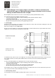
Encoder connection examples are shown below. All signal wires shall be included inside a single shielded cable. Power
supply to the encoder may also be included in the same cable.
Standard connection
Encoder 24 ppr.
:55
+24V
:51
EA+
:54
EB-
INVERTER
blue
+V
0V
red
:56
0V
:53
EB+
:52
EA-
G
yellow
A+
terminal box
D2L
X1
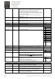
Standard connection
Encoder 600 ppr. or more
:55
+24V
:51
EA+
:54
EB-
INVERTER
black
blue
+V
A-
0V
red
:56
0V
:53
EB+
:52
EA-
G
yellow
A+
green
B+
white
B-
terminal box
D2L
X1
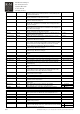
In standard encoders, there are also "zero outputs (Z+, Z-)", which should be left disconnected. If the encoder does not
have negative channels (A- and B-), EA- and EB- must be connected to 0V at motor terminal box (alternative
connection).
In order to avoid fault situations, the cable between the encoder and inverter must be
- as far as possible from the cables of motor and braking resistor (minimum distance >20cm)
- a shielded and twisted cable
- grounded (the shield) at both ends, 360
°
grounding on inverter terminal
- the shield should be grounded always when going through terminals
Some problems may occur when using shielded flat cable or in situations where the encoder cable has been placed too
close (< 5cm) to the motor cables and braking resistor cables.
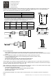
1.16.3 Proximity switch
In modernisation cases there might be proximity switch as pulse sensor of motor.