
Service Manual Instruction Manual


R&M Materials Handling, Inc.
4501 Gateway Boulevard
Springfield, Ohio 45502
P.: (937) 328-5100
FAX: (937) 325
-
5319
22/83
R&M Materials Handling, I
nc. reserves the right to alter or amend the above information without notice.
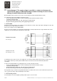
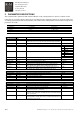
Inverter needs information about the motor rotation speed for stall, speed difference and over speed supervision. Type
markings of the speed supervision sensors (not needed in applications with bearing sensor or encoder) and fixing
distance from the pulse wheel (air gap) are shown in the table below.
Proximity switch air gap
Honeywell 3GT101DC
5
12
35
29
Honeywell 3GT101DC 0.5 ... 1.0 mm
Schönbuch INSOR88 ICDM 8802 0.5 ± 0.1 mm
Baumer IFRM08N1501/L 0.5 ± 0.1 mm
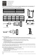
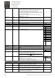
Note that the Honeywell-sensor cable is lengthened and the wire colours are not equal to other
sensors. However, colour markings corresponding to the other sensors have been added to
wire ends (not necessarily, if cable has been shortened afterwards). The connection of
Honeywell-sensor and the cable markings are shown in the table below.
Signal name Sensor Cable Colour marking Terminal number
+24V Red Brown Brown KAE234:6
PULSE Green Green Black KAE234:1
40
8
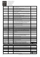
Schönbuch INSOR ICDM 8802
0V Black White Blue KAE234:2
Red
Green
Black
Brown
Green
White
6
1
2
3
4
7
+
0V
+15V
OUT
0V
Honeywell 3GT101DC
A5
INVERTER
+24V
EA+
OV
Brown
Black
Blue
6
1
2
3
4
7
+
0V
+15V
OUT
0V
A5
INVERTER
+24V
EA+
OV
M8x1
30
Baumer IFRM08N1501/L
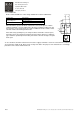
Note the following details
- buffer amplifier must be located as close the proximity switch as possible (maximum distance 3m)
- sensor cable must be located as far from the motor cables and braking resistor cable as possible (minimum distance
> 20cm)
In order to avoid fault situations, the cable between the encoder and inverter must be
- as far as possible from the cables of motor and braking resistor (minimum distance >20cm)
- a shielded and twisted cable
- grounded (the shield) at both ends, 360
°
grounding on inverter terminal
- the shield should be grounded always when going through terminals
Some problems may occur when using shielded flat cable or in situations where the encoder cable has been placed too
close (< 5cm) to the motor cables and braking resistor cables. Cabling methods and distances determine the best way to
ground the shielded cable; at both ends or only at one end.
Buffer amplifier pulse output can be measured during driving. If the pulse sequence is not uniform and for instance longer
pulses occur every now and then, the reason may be one of following:
- an incorrect air gap (proximity switch)
- the sensor is not properly on the top of the pulse wheel (proximity switch)
- disturbances are transferred to the sensor cable
- the pulse wheel is faulty
Honeywell 3GT101DC Hall-sensor requires tooth movement past the sensor. A motionless tooth can not generate a
pulse.