
Service Manual Instruction Manual


R&M Materials Handling, Inc.
4501 Gateway Boulevard
Springfield, Ohio 45502
P.: (937) 328-5100
FAX: (937) 325
-
5319
28/83
R&M Materials Handling, I
nc. reserves the right to alter or amend the above information without notice.
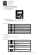
3 PARAMETER DESCRIPTIONS
This manual describes parameters with software Ind2V081. Under control panel there is sticker for software version.
Parameters are assorted to Groups. All Groups are not always listed in control panel. Groups are shown in control panel
according to password level and selected functions. This feature makes visible parameter menu simple and only needed
parameters are shown.
Letter front of the code number describes variable type
A = Application E = Expander R = Reference
B = Button G =Group S = System
C = Counter I = Info T = Trip Counter
D = DynACode P = Parameter V = Value
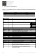
Label Code Function/Description Adjustment range
G2.1 General Parameters
Password P2.1.1 Default 768
Service 2156, shows also group G2.3. Expert and G2.4 Synchronization
Supply Voltage V2.1.2 Power unit nominal voltage F 380V – 500V
Device V2.1.3 Device Industrial
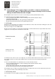
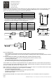
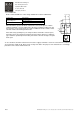
Input Set P2.1.4 Input Set selection, see chapter “Control methods” 1 = EP
2 = EP3
3 = Multistep
Analog Input Sel P2.1.5 Analog input selection
0 = Not used
1 = Multicare
2 = Load
3 = Multicare&Load
Slow speed freq P2.1.6 Speed when one of slow down limit switches (S11/S21) is open 0 – 250 Hz
Multistep 2 freq P2.1.7 2
nd
preset speed. Multistep speed setting. 0 – 250 Hz
Multistep 3 freq P2.1.8 3
rd
preset speed. Multistep speed setting. 0 – 250 Hz
Multistep 4 freq P2.1.9 4
th
preset speed. Multistep speed setting. 0 – 250 Hz
Accel Time 1 P2.1.10 Acceleration ramp is defined from zero to motor nominal frequency
P2.2.2. Shorter values than the factory setting must not be used.
1-300 s
Decel Time 1 P2.1.11 Deceleration ramp is defined from motor nominal frequency P2.2.2 to
zero. Shorter values than the factory setting must not be used.
1-300 s
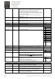
G2.1.12 Multicare
Test Voltage Min B2.1.12.1 1.00V is given to Analog output Aout2 by this button. Off / On
Test Voltage Max B2.1.12.2 9.00V is given to Analog output Aout2 by this button. Off / On
Ain 1 Value V2.1.12.3. Value of analog input Ain1 voltage V
Min Value Volt 1 P2.1.12.4. Ain1 value when test voltage min has been selected in the other drive. 0 – 10 V
Max Value Volt 1 P2.1.12.5. Ain1 value when test voltage max has been selected in the other drive. 0 – 10 V
G2.2 Motor Parameters
Motor Nom Volt P2.2.1 Nominal motor voltage Un from motor rating plate. 0 – 750 V
Motor Nom freq P2.2.2 Nominal motor frequency fn from motor rating plate 0 – 250 Hz
Motor Nom Speed P2.2.3 Nominal motor speed n from motor rating plate 0 – 6000 rpm
Motor Nom Curr P2.2.4 Nominal motor current In from motor rating plate. In multimotor drives
nominal currents must be summarized.
Nom Flux Curr P2.2.5 Motor nominal flux current Io, same as no-load current or magnetizing
current from motor rating plate. In multimotor drives nominal flux currents
must be summarized.
Start Current P2.2.6 Start current. Current level, which is used in motor starting situation.
Hoisting application: default value is motor’s nominal current, but not over
nominal current of the inverter.