
Service Manual Instruction Manual


R&M Materials Handling, Inc.
4501 Gateway Boulevard
Springfield, Ohio 45502
P.: (937) 328-5100
FAX: (937) 325
-
5319
30/83
R&M Materials Handling, I
nc. reserves the right to alter or amend the above information without notice.
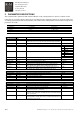
Freq 1 P2.3.5 Flux current mode frequency limit in percentage of nominal frequency.
Between frequencies Freq 1 and Freq 2 drive is controlled with special
flux current control method.
0 – 100 %
Freq 2 S1 P2.3.6 Mixed current/voltage mode frequency limit in percentage of nominal
frequency in direction S1. Must not be changed.
0 – 100 %
Freq 3 S1 P2.3.7 U/f-control mode frequency limit in percentage of nominal frequency in
direction S1. Must not be changed.
0 – 100 %
Zero Flux Curr P2.3.8
Relative value of flux current of motor. Typical value of this current control
method is 80 %. Parameter is not related to motor real physical values.
Must not be changed.
0 – 100 %
Stray Flux Curr P2.3.9 Relative value of stray flux current of motor. Typical value of this current
control method is 40 %. Parameter is not related to motor real physical
values. Must not be changed.
0 – 100 %
Freq 2 S2 P2.3.10 Mixed current/voltage mode frequency limit in percentage of nominal
frequency in direction S2. Must not be changed.
0 – 100 %
Freq 3 S2 P2.3.11 U/f-control mode frequency limit in percentage of nominal frequency in
direction S2. Must not be changed.
0 – 100 %
Zero Speed Curr P2.3.12 Relative value of motor current used in small frequencies % of motor
nominal current. Must not be changed.
0 – 250 %
Min Current Ref P2.3.13 Minimum value of motor current used in current control area % of motor
nominal current. Must not be changed.
0 – 100 %
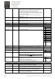
Accel Comp TC P2.3.14 Acceleration compensation time constant, which describes rotating
masses of drive system. Physical description of this parameter is a time,
which is needed to accelerate rotating masses from zero to nominal
frequency with motor nominal torque. Must not be changed.
0 – 300 s
Ref Angle S1 P2.3.15 Voltage / current angle difference S1. 1536 equals 90 angle. Used in
direction changes. Must not be changed.
0 – 3000
Ref Angle S2 P2.3.16 Voltage / current angle difference S2. 1536 equals 90 angle. Used in
direction changes. Must not be changed.
0 – 3000
Flux Curr Damp P2.3.17 Flux Current Ctrl stabilator time constant in milliseconds. Must not be
changed.
0 – 400 ms
Stop DC-Freq P2.3.18 Defines the frequency at witch DC-braking starts. 0 – 250 Hz
Start Freq S1 P2.3.19 Defines the output frequency during brake opening delay to direction S1. 0 - Max Freq S2, Hz
Start Freq S2 P2.3.20 Defines the output frequency during brake opening delay to direction S2. 0 - Max Freq S2, Hz
Brake Stop Freq P2.3.21 When stopping the contact of the relay output ROB2 opens when the
output frequency of drive goes below the value set in this parameter.
0 - Max Freq S2, Hz
ESR Point Freq P2.3.22 Defines ESR (field weakening) point frequency in percents of motor
nominal frequency.
0 – 250 %
ESR Point Volt P2.3.23 Defines ESR (field weakening) point voltage in percents of motor nominal
voltage.
0 – 250 %
IrAdd Motor P2.3.24 With small speeds and heavy load the hoist movement does not have
enough voltage to produce sufficient torque. Raising the value of this
parameter increases the voltage. Must not be changed.
0 – 200 %
IrAdd Generator P2.3.25 If motor voltage at generator area is too high, reducing value of
parameter decreases the voltage.
0 – 200 %
Ramp Stretching P2.3.26
See Chapter "Ramp Stretching". Not used in hoisting
0 – 50 %
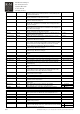
Switching Frequency
P2.3.27 Must not be changed from factory setting 3.6 kHz
DeadTime Comp P2.3.28 Dead time compensation time delay. Parameter value does not tell the
actual time used in compensation.
0 – 10000
DeadTime CurrLim P2.3.29 Parameter that is used to control the current waveform in dead time
compensation.
0 – 1000
Brake Chopper P2.3.30 Defines when braking chopper is allowed to be activated.
Always while drive is in ready state or only while running.
1 = Yes (Run)
0 = Yes (Ready)
Autotuning P2.3.31 Autotuning must not be done with ControlMaster Plus - Hoisting. 0 = Not Done
G2.4 Synchronization (Not viewable witout OPT-D1 option board)
Address P2.4.1 SystemBus node address. Synchro is in use when the address is >0, the
OPT-D1 option board is installed in the slot E and input DID1 is on.
0 - 4
Next Address P2.4.2. Next system bus node address 0 - 4
Last Address P2.4.3. Last system bus node address 0 - 4
Nominal Speed P2.4.4. Nominal speed of the hoist 0,00 – 300,00 m/min
Displacement Lim P2.4.5. Maximum displacement error between synchronized drives. Only master
unit will use this parameter.
1 – 100 mm
Gain P2.4.6. Correction signal gain. Only master unit will use this parameter. 0 – 10000
Sync Activation P2.4.7. Synchro activation state. If “During Run” is selected, activation of the unit
can be done while driving. In this case, all the units have to have “During
Run” selected. Default = “During Stop”
0 = During Stop
1 = During Run