
Service Manual Instruction Manual


R&M Materials Handling, Inc.
4501 Gateway Boulevard
Springfield, Ohio 45502
P.: (937) 328-5100
FAX: (937) 325
-
5319
31/83
R&M Materials Handling, Inc. reserves the right to alter or amend the above information without notice.
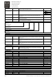
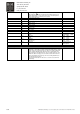
Min Freq Offset P2.4.8
Parameter defines how much below minimum frequency can correction to
frequency output of the drive be made.
0,00 – 20,00 Hz
SystemBus Speed P2.4.9. SystemBus communication speed. Default = 3 Mbit/s 0 = 1,5 Mbit/s
1 = 3 Mbit/s
2 = 6 Mbit/s
3 = 12 Mbit/s
Max Pos Error V2.4.10.1. Current position error of the hoist with the largest displacement to
synchronization reference position. Only master unit displays this
information.
Mm
Pos Error 1-4 V2.4.10.2-5 Unit 1-4 current position error to Synchro position. Only master unit
displays this information.
mm
Peak Pos Error 1-4 V2.4.10.6-9 Unit 1-4 peak position error to Synchro position since last power off. Only
master unit displays this information.
mm
Synchro Status V2.4.10.10. 0 0 0 0 0 00000-11111
1=SystemBus
address >0
Nominal speed >0
SSU board OK
1=SystemBus
working properly
1= Unit is a Master
1= Unit is a Follower
1=Synchro is active
in this station
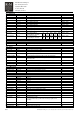
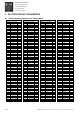
G4. Monitoring
G4.1 Parameter backup
Load Default Par B4.1.1 Restores Default Parameters to Active Parameters from the Control Unit
memory. Default Parameters are the parameters, which have been saved
in the factory.
Save User Par B4.1.2 Saves Active Parameters in the Control Unit as User Parameters. Final
parameters for the application must be saved as User Parameters after
start-up.
Load User Par B4.1.3 Restores User Parameters to Active Parameters from the control unit
memory. User Parameters are the parameters, which have been saved
after start-up.
G4.1.4 Factory Default
Save Default Par B4.1.4.1 Saves Active Parameters in the Control Unit as Default Parameters.
Default Parameters are the parameters, which must be saved in the
factory. For factory use only.
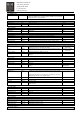
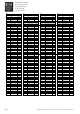
G4.2 Analog I/O
Ain1 Value V4.2.1 Value of analog input Ain1 0 – 10 V
Ain2 Value V4.2.2 Value of analog input Ain2 0 – 10 V
Aout1 Value V4.2.3 Value of analog output Aout1 0 – 20 mA
Aout2 Value V4.2.4 Value of analog output Aout2 0 – 10 V
G4.3 Relay output
ROB1 State V4.3.1 State of relay output ROB1 0=OFF, 1=ON
ROB2 State K7 V4.3.2 State of relay output ROB2, K7 0=OFF, 1=ON
ROC1 State V4.3.3 State of relay output ROC1 0=OFF, 1=ON
ROD1 State V4.3.4 State of relay output ROD1 0=OFF, 1=ON
ROE1 State V4.3.5 State of relay output ROE1 0=OFF, 1=ON
ROE2 State V4.3.6 State of relay output ROE2 0=OFF, 1=ON
ROE3 State V4.3.7 State of relay output ROE3 0=OFF, 1=ON
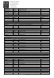
G4.4 Operate counters
Not used
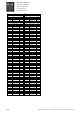
G4.5. Fault Counter
Fault Counter V4.5.1. – 4.5.24 Fault counter value.
Other faults V4.5.25 Other faults
Total Faults V4.5.26