
Service Manual Instruction Manual


R&M Materials Handling, Inc.
4501 Gateway Boulevard
Springfield, Ohio 45502
P.: (937) 328-5100
FAX: (937) 325
-
5319
32/83
R&M Materials Handling, I
nc. reserves the right to alter or amend the above information without notice.
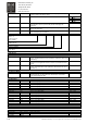
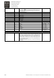
G4.7. Digital Input
S1 V4.7.1.1. State of digital input S1 0=OFF, 1=ON
S2 V4.7.1.2. State of digital input S2 0=OFF, 1=ON
DIA3 V4.7.1.3. State of digital input DIA3 0=OFF, 1=ON
DIA4 V4.7.1.4. State of digital input DIA4 0=OFF, 1=ON
DIA5 V4.7.1.5. State of digital input DIA5 0=OFF, 1=ON
OK V4.7.1.6. State of digital input OK 0=OFF, 1=ON
DID1 V4.7.1.7. State of digital input DID1 0=OFF, 1=ON
DID2 V4.7.1.8. State of digital input DID2 0=OFF, 1=ON
DID3 V4.7.1.9. State of digital input DID3 0=OFF, 1=ON
DID4 V4.7.1.10. State of digital input DID4 0=OFF, 1=ON
DID5 V4.7.1.11. State of digital input DID5 0=OFF, 1=ON
Basic Board V4.7.3. State of board A inputs
Corresponding X1 terminals
S1
8
S2
9
DIA3
10
DIA4
11
DIA5
12
0=OFF, 1=ON
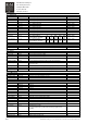
Extension Board V4.7.4. State of board D inputs
Corresponding X1 terminals
DID1
38
DID2
39
DID3
40
DID4
41
DID5
42
0=OFF, 1=ON
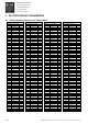
G4.8. SSU
Overspd Lim 1 V4.8.1. Overspeed limit 1 level. Percent of Max Freq S2 0 – 140 %
Overspd Lim 2 V4.8.2. Overspeed limit 2 (ESR) value. Percent of Max Freq S2 0 – 140 %
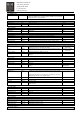
G4.9. Service
Phase U Curr V4.9.1. Phase U current of inverter output A
Phase V Curr V4.9.2. Phase V current of inverter output A
Phase W Curr V4.9.3. Phase W current of inverter output A
Encoder Speed V4.9.4. Pulse frequency from pulse sensor. Both A and B channel must be in
use.
Hz
HeatSinkTempMax V4.9.5. Recorded heatsink temperature highest peak value during run.
°C
HeatSinkTempMin V4.9.6. Recorded heatsink temperature lowest peak value when power is
connected to drive.
°C
IGBT Temp Max V4.9.7. Recorded calculated IGBT temperature highest peak value.
°C
IGBT Temperature V4.9.8. Actual IGBT temperature
°C
SlipAdjustChange V4.9.9. Slip adjust difference compared to Slip adjust parameter. %
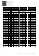
G4.9.10 Max Current.
Max Current G4.9.10.1. Recorded maximum current A
Max Current Freq G4.9.10.2. Frequency at recorded maximum current. Hz
Max Current Torq G4.9.10.3. Torque at recorded maximum current. %
G4.9.11 Encoder
V4.9.11.1 Not used.
V4.9.11.2 Not used.
V4.9.11.3 Not used.
V4.9.11.4 Not used.
V4.9.11.5 Not used.
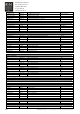
Freq Ref V4.11. Frequency reference Hz
Speed Req V4.12. Not used.
Distance counter V4.13. Not used m
DC-Link Voltage V4.14. Actual value of measured DC-link voltage. V
Heat Sink Temp V4.15. Temperature of heat sink.
°C
MotorTemperature V4.16. Calculated motor temperature in percent of maximum %
Motor Power V4.17. Calculated actual power. % of nominal power of unit %
Motor Voltage V4.18. Calculated motor voltage V
Motor Torque V4.19. Calculated motor torque
+/- motor nominal torque, positive when motoring, negative when
generating.
%
Motor Current V4.20. Measured motor current A
Motor speed V4.21 Calculated motor speed Rpm
Output frequency V4.22 Output frequency to the motor Hz