
Service Manual Instruction Manual


R&M Materials Handling, Inc.
4501 Gateway Boulevard
Springfield, Ohio 45502
P.: (937) 328-5100
FAX: (937) 325
-
5319
54/83
R&M Materials Handling, I
nc. reserves the right to alter or amend the above information without notice.
3 TROUBLESHOOTING
Warning! High voltages inside Frequency converter. Wait for at least five minutes
after the supply voltage has been switched off before service actions. The display in
the operating condition (lights on) indicates a dangerous voltage on the DC-bus.
When display turns off, the DC-bus voltage is approximately 100V. Note also that
there is always a dangerous voltage in the braking resistor when the DC-bus is
charged.
3.1 Field repair actions
The purpose of troubleshooting and field repair actions is primarily to determine whether the drive or external
devices in fact cause the problems. After that, the next step is to detect the possibly damaged components inside
the drive. If any damage inside the drive is caused by the environment (motor failure, brake failure, power supply
problems etc.) it is very important to repair/change faulty items to prevent reoccurring problems.
The best way to repair a faulty inverter is to replace it with a new one. If the fault can be located, it is also possible
to replace some of the components. When replacing an inverter or a Control unit with a new one, the parameter list
of the existing drive is needed so that the parameter settings can be copied to the new one.
If parameters have been copied to the keypad before damage, it may be used for uploading the parameters to the
spare part inverter (requires same software versions).
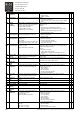
3.2 Typical functional problems
Inverter does not start when mains is connected.
Check mains voltage between terminal L1, L2 and L3
Indicator “Ready” is on and Indicator “Fault” is off, but motor does not run.
Check control mode selection
Check voltage at run command terminals X1:8 and X1:9
Check state of digital inputs from parameter V4.7.12
Motor runs poorly
Check that load is not over nominal
Check that all cables are connected correctly and the junctions are reliable
Check that all motor dependant parameters are correct
Check the voltage of the slowdown limit switch input
Check state of digital inputs from parameter V4.7.13
Check that motor’s brake opens completely
Check that minimum speed parameters do not have too small values
Check u/f-curve tuning
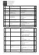
If the main girder is new, it might be necessary to drive trolley several times with no load from end to end, before beginning of
u/f-curve tuning
Some parameters are not accessible or changing is not possible
Check password that password has value 2156
Check that parameter value is inside the limits
Parameter value can not be changed in RUN state
Parameter value change must be confirmed with “Enter” button
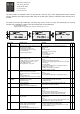
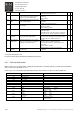
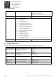
3.3 Inverter fault codes
If any of the following failures is found, the inverter displays the fault code and closes the mechanical brake causing
the movement to stop. If several faults occur one after another, the latest one is displayed, the others are stored to
fault history page.
When inverter fault supervision trips, the FAULT indicator turns on and the blinking fault code “F xx“ (xx = fault
number) appears on the display.