
Service Manual Instruction Manual


R&M Materials Handling, Inc.
4501 Gateway Boulevard
Springfield, Ohio 45502
P.: (937) 328-5100
FAX: (937) 325
-
5319
56/83
R&M Materials Handling, I
nc. reserves the right to alter or amend the above information without notice.
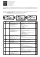
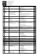
undervoltage trip
F 10 Input line
supervision
One input line phase is missing. Check:
• supply voltage
• mains connection.
X
F 11 Output phase
supervision
Current supervision has sensed that at least
one of the motor phases has no current
Check:
• motor cable connections
• measure motor phase currents and compare to display
value
X
F 12 Braking
chopper
supervision
Braking chopper or braking resistor circuit
has failed. Test pulse measures transistor
collector voltage. Fault appears if
• braking resistor is broken
• braking chopper is broken
• braking resistor is not installed
Reset: switch power off and restart after the lamps of
display are off.
Check:
• braking resistor and insulation resistance
• measure braking transistor IGBT and free wheeling
diodes
• If resistor is OK, then the chopper is broken
• Contact authorized
service
X
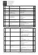
F 13 Inverter
undertemperatu
re
Temperature of heat sink is below
acceptable operating level (-10°C /14°F)
Check
• ambient temperature
• cubicle heating
X
F 14 Inverter
overtemperatur
e
Temperature of heat sink is over acceptable
operating level
+90°C (194°F).
Overtemperature warning is issued when the
heat sink temperature exceeds +85°C (185°F)
Check:
• ambient temperature
• inverter cooling fan operation
• cooling air flow through heat sink
• heat sink is not dusty
X
F 22
F 23
EEPROM
checksum fault
Parameter save error
• interference fault
• component failure (control unit)
After power off the inverter will automatically reset
parameter settings. The drive does not work properly nor
enable driving after this fault.
Check:
• all parameter settings.
• +24V voltage output loading
• If the fault comes again, contact authorized
service
center.
X
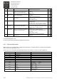
F 24 Changed data
warning
Changes may have occurred in the different
counter data due to mains interruption
No special actions required. Take a critical attitude to the
counter data.
X
F 25 Microprocessor
watchdog-fault
• interference fault
• component failure (control unit)
Reset: switch power off and restart after the lamps of
display are off.
If the fault comes again, contact service.
X
F 26 Power Unit
Fault
X
F 31 IGBT
temperature
Too high temperature in IGBT. A hardware
temperature measurement has tripped.
Reset: switch power off and restart after the lamps of
keypad are off. Check:
• motor loading
• brake operation
• inverter heatsink
• inverter cooling fan operation
• environment temperature
X
F 32 Fan cooling
fault
Cooling fan of the frequency converter do
not work, when ON command has been
given
If the fault comes again, contact authorized
service. X
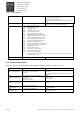
F 35 Application
fault
Run-time exception in the application
program
Contact authorized service. X
F 36 Control Unit Faulty Control Unit. Contact authorized service. X
F 37 Device changed
Option board changed. Reset the fault X
F 38 Device added Option board added. Reset the fault X
F 39 Device
removed
Option board removed. Reset the fault X
F 40 Device
unknown
Unknown option board or drive. Check board and drive type. X
F 41 IGBT
tempetature
Too high temperature in IGBT transistors.
• long duration overload
• lowered cooling
• high environment temperature
Reset: switch power off and restart after the lamps of
keypad are off. Check:
• motor parameters
• u/f curve settings
• motor loading
• brake operation
• inverter heatsink
• inverter cooling fan operation
• environment temperature
X
F43 Encoder failure
Encoder failure.
Subcodes:
• S1 = EA+/- is missing
• S2 = EB+/- is missing
Check:
• Encoder cabling
• Brake opening
• Encoder mechanical assembly
X