
Service Manual Instruction Manual


R&M Materials Handling, Inc.
4501 Gateway Boulevard
Springfield, Ohio 45502
P.: (937) 328-5100
FAX: (937) 325
-
5319
64/83
R&M Materials Handling, I
nc. reserves the right to alter or amend the above information without notice.
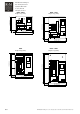
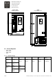
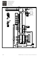
11 DRAWINGS
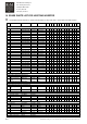
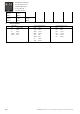
4.1 Description of terminals
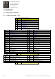
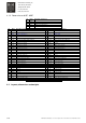
4.1.1 Power classes 002F - 011F
No Name Description, signal level
PE
L1 L1 Power supply, phase 1
L2 L2 Power supply, phase 2
L3 L3 Power supply, phase 3
B+ B+ Braking resistor
R- R- Braking resistor
U/T1 U/T1 Motor output, phase 1
V/T2 V/T2 Motor output, phase 2
W/T3 W/T3 Motor output, phase 3
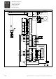
No
Name Description, signal level No
Name Description, signal level
1 BL1 AC brake supply, phase 1 31 BD1 DC brake supply 1
2 BL2 AC brake supply, phase 2 32 BD2 DC brake supply 2
3 BL3 AC brake supply, phase 3 33 T1 Thermistor input
4 T12 Reserved for thermistors connections 34 T2 Thermistor input
5 OLE External control voltage, 42/48/115/230Vac 35 ONE Neutral of external control voltage OLE
6 OLE External control voltage, 42/48/115/230Vac 36 ONE Neutral of external control voltage OLE
7 RDY Stop with brake 37 ES External Stop
8 S1 Direction 1 run command 38 DID1 Free input
9 S2 Direction 2 run command 39 DID2 (S11) Slowdown signal, direction 1
10 DIA3 Accelerate / speed 2 40 DID3 (S21) Slowdown signal, direction 2
11 DIA4 Not used / hold / speed 3 41 DID4 (S12) Stop limit signal, direction 1
12 DIA5 Not used / speed 4 42 DID5 (S22) Stop limit signal, direction 2
13 43
14 44
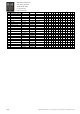
15 K7-A1 Coil of brake contactor K7 45 ROB1-21 Not used
16 ROB1-22 Not used 46 ROB1-23 Not used
17 ROD1-28 Free NO-contact of relay ROD1 47 ROD1-29 Free NO-contact of relay ROD1
18 K7-153 Free NO-contact of K7 48 K7-154 Free NO-contact of K7
19 K7-163 Free NO-contact of K7 49 K7-164 Free NO-contact of K1
20 K71-13 Free NO-contact of K71 50 K71-14 Free NO-contact of K71
PE
21 PUR Not used 51 EA+ Encoder channel A+
22 +15V Not used 52 EA- Encoder channel A-
23 AIN1+ Multicare speed reference input, 0...+10V 53 EB+ Encoder channel B+
24 AIN2+ Not used 54 EB- Encoder channel B-
25 AIN- Common for analog inputs 55 +24V +24V output for encoder
26 AOUT Multicare speed reference output 0...+10V 56 0V Common for encoder supply
27 0V Common for analog output 57 +24V External supply for Control module
PE