
Service Manual Instruction Manual

R&M Materials Handling, Inc.
4501 Gateway Boulevard
Springfield, Ohio 45502
P.: (937) 328-5100
FAX: (937) 325
-
5319
9/83
R&M Materials Handling, Inc. reserves the right to alter or amend the above information without notice.
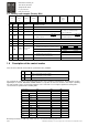
1.5 Factory code example (Factory: D2L)
D2L 007 F V 52 A 0 N 1 L
HS01 (ELE83) (ELE83) (ELE02)
(ELE97)
(EL32)
1-3 4-6 7 8 9,10 11 12 13 14 15
Pos. Code
Feature
code
Feature Available properties
1-3
D2L
HS01 Device name D2L
4-6
007
(ELE83) Power rating class 002 - 055
ELE83 values are composed of two features,
Power rating class and Supply voltage.
e.g. 007F = ELE83 value
7
F
(ELE83) Supply voltage F 380 – 500 VAC, 50/60 Hz
8
V
(ELE02) Control voltage
Y
P
42VAC, 50/60 Hz
48VAC, 50/60 Hz
ELE02 value
48
T
V
115VAC, 50/60 Hz
230VAC, 50/60 Hz
ELE02 value
115
230
9,10
52
Revision code The latest revision may differ.
11
A
Braking resistor type A External resistor
12
0
Mounting 0 Standard
13
N
(ELE97)
(EL32)
EMC level and
grounding
ELE97 value EL32 value
S Standard, without EMC filters (grounded network) NONEU GRD
N EMC, Second environment (grounded network) EU GRD
0 IT network (non-grounded network)
NONEU NONGRD
EU NONGRD
14
1
HS27 Boards
1
5
Standard, with speed supervision
System bus, with speed supervision
15
L
Special L Varnished boards
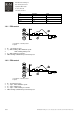
1.6 Description of the control modes
There are three different control methods (command modes) available:
1 EP2 Electronic motor potentiometer function.
Stepless control using a 2-step controller.
2 EP3 Electronic motor potentiometer function.
Stepless control using a 3-step controller.
3 MS Multistep control (4 steps)
The control mode of inverter is selected by parameter P2.1.4. See chapter Control methods. The parameters assigns
digital inputs S1, S2, OK, DIA3-DIA5 and DID1-DID5.It is not possible to chance the functions of the inputs separately.
The state of inputs can be checked from parameters V4.7.12 and V4.7.13. The input assignment according to the
selected mode is explained in the following table:
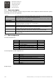
Control mode EP EP3 MS
Parameter P2.1.4 1 2 3
Signal Terminal
S1 X1:8 S1 S1 S1
S2 X1:9 S2 S2 S2
OK X1:7 OK OK OK
DIA3 X1:10 AP AP MS2
DIA4 X1:11 Not used HOLD MS3
DIA5 X1:12 Not used not used MS4
DID1 X1:38 FWE FWE FWE
DID2 X1:39 S11 S11 S11
DID3 X1:40 S21 S21 S21
DID4 X1:41 S12 S12 S12
DID5 X1:42 S22 S22 S22
Desired speed levels for multi-step control mode are selected with following parameters: