www.r-techwelding.co.uk email: sales@r-techwelding.co.
- 2 -
Thank you for selecting the R-Tech MTS255S Inverter Mig (Synergic) - MMA - TIG Welder.
Product Description Premium features include:• • • • • • • • • • • Inverter power source – more efficient to operate, provides smoother weld characteristics. Heavy duty wire feed unit for long working life and consistent wire feeding.
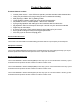
Installation Technical Specifications Model No. R-Tech POWER MTS255S Input 240V 1 ~ AC 50/60Hz Operation Rated Input Current Rated Output Current Duty Cycle 35% @ 40OC Duty Cycle 100% @ 40OC 32AMPS 250 AMPS 250A (MIG/TIG) ,200A(MMA) 160A (MIG/TIG),130A(MMA) Output current Range MIG: 30-250 AMPS MMA: 10-200AMPS TIG: 10-250 AMPS No Load Voltage MIG Voltage Adjustment Range Suitable Wire Diameter 60~80V 14V - 29V± 3V 0.6mm 0.8mm 1.
Transport & Unloading Never underestimate the weight of equipment, never move or leave suspended in the air above people. Use recommended lifting equipment at all times. WARNING! Falling Equipment can cause injury. Never lift welder with gas bottle attached. Never lift above personnel. Tilting Machine must be placed on a secure level surface or on a recommended undercarriage/trolley. This machine may topple over if this procedure is not followed.
Input Connections Make sure the voltage, phase and frequency of input power is as specified on machine rating plate located at rear of machine. Have a qualified electrician provide suitable input power as per national electrical codes. Make sure machine is earthed / grounded. Make sure fuse or circuit breaker is correct rating for machine. Using fuses or circuit breakers smaller than recommended will result in nuisance shut off from welder inrush currents even if welding at low amperages.
Controls and Settings Front Panel Fig 1 1) Voltage /MMA Arcforce/TIG down slope Display • The meter on the front panel can indicate the actual welding voltage or preset MIG voltage. The indicating • Display MMA Arcforce • Display TIG down slope time number has the precision of 0.1V .The meter indicates the preset during no welding.
7) MIG/TIG/STICK Process Selector Each icon graphically represents each process. The top function represents MIG. The middle function represents TIG. The bottom function represents Stick. 8) Voltage - When lit LED display will show welding voltage 9) Tig welding current / MIG Wire Speed Trim Adjustment Knob For MIG Synergic operation, the amps are directly tied to the wire speed feed. Using this knob you can fine tune the wire feed speed +/- from synergic setting.
on, release the trigger and you can then weld without holding the trigger down. To stop, the trigger must be pressed again and then released. The 4T function in TIG mode acts similarly, but in conjunction with the down slope timer. As the torch trigger is pressed for the second time, the trigger should be held in until the downslope timer completes its cycle. The trigger may then be released to end the arc. Releasing before the down slope is finished will terminate the arc immediately.
Rear machine connections Fig2 1 Mains input cable (240V AC input ) Fit the required plug as per your electrical installation 2 On/Off Switch 3 Fuse Holder 5A fuse for wire speed 4 Gas input connector Connect input gas hose ensuring connection is tight - 11 -
Connections for TIG (GTAW) Welding Fig 3 1) Gas outlet Connect the TIG torch gas hose quick release connector 2) MIG Torch Euro Connector (NOT used in TIG mode) 3) Positive power connector + Connect the earth lead to by inserting and twisting until tight and the earth clamp to work/bench 4) Torch control socket 7-Pin Connect torch control plug or Remote Foot Pedal plug.
Connections for STICK MMA (SMAW) Welding Fig 4 1 Gas outlet (NOT used in MMA mode ) 2 MIG Torch Euro Connector (NOT used in MMA mode ) 3 Positive power outlet – Connect electrode holder lead 4. Remote connection (NOT used in MMA mode) 5.
Connections for STICK MIG /MAG Welding 1 Gas outlet (NOT used in MIG mode ) 2 MIG Torch Euro Connector - Connect Mig Torch 3 Positive 4. Remote connection (NOT used in MIG mode) 5.
Using the wire feed unit TO INSTALL WIRE: 1. Loosen top tensioner arm, rotating counter-clockwise 2. Flip tensioner down, releasing top drive rolls. 3. Raise top drive rolls. 4. Inspect the drive roll to make sure that the groove size matches the wire diameter. Reversal of the lower roller may be necessary. To reverse the roller, remove the thumb screw securing the drive roll. Pull the drive roll off, and flip the drive roll over. Reassemble and tighten roller. If larger roller is needed, contact R-Tech.
Connections for using gas/gasless wire 1. Gas type wire Connect as per diagram above, A is power outlet, B is + to torch Fit earth lead to - negative connector on front of machine 2. Gasless type wire (reverse polarity required for gasless wire) Connect brass bar from A to C so torch is negative Fit earth lead to + positive connector on front of machine Note: Ensure machine is disconnected from mains before changing torch polarity.
Operation SAFETY PRECAUTIONS WARNING! ELECTRIC SHOCK CAN KILL Do not touch electrically live parts or electrode with skin or wet clothing. Insulate yourself from work and ground Always wear dry insulating gloves WARNING! FUMES AND GASES can be dangerous Keep your head out of fumes & gases produced from welding. Use ventilation or exhaust to remove fumes & gases from breathing zone and general area. WARNING! WELDING SPARKS can cause fire or explosion Keep flammable material away from work area.
Adjust wire feed speed to suit voltage/wire diameter chosen. Wire reel holder - remove retainer screw cap and fit wire reel and refit securing screw cap. The reel holder features an internal adjustable braking system so that reel of wire stops quickly when the torch trigger released, otherwise the wire reel would continue for a few seconds causing wire to come off the sides. Wire feed assembly - make sure the rollers are the correct size for the wire diameter selected.
The benefits of welding with a remote foot pedal is that of greater control of the amount of heat going into the work - Press the pedal fully to start welding; upon weld pool formation you can slightly release the pedal to decrease the amperage to sustain a perfect weld pool and increase it again as required to sustain the weld characteristics.
remember the last settings if it is turned off. How to setup the Synergic and Manual functions: 1. Turn unit on. Wait for it to go through the power up cycle. 2. Select the MIG icon with the Process Selector button. 3. Select the wire diameter of the wire being used. 4. Select the filler wire type. 5. Select 6. 4T requires the trigger to be pressed to start the arc. Once arc is started the trigger should be released to continue weld.
Maintenance Routine and periodic maintenance WARNING! ELECTRIC SHOCK CAN KILL Turn the input power OFF at the mains switch & fuse box before working on this equipment. Have a qualified electrician install & service this equipment. Allow machine to sit for 5 minutes minimum to allow the power capacitors to discharge before working inside this equipment. Do not touch electrically live parts 1.
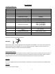
The second column labeled possible cause lists the obvious external possibilities that may contribute to the machine symptom Step 3 Recommended course of action This column provides a course of action for the possible cause, generally it states to contact R-Tech welding for repair of machine. Troubles Cause Remedy 1.Fan does not work properly 1.the fan line lose 2.Fan breakage 1.Connect the line 2.Change the fan 2.No indicating on the front panel 1.the power line lose 2.Indicating light broken 3.
Electrical Schematic Diagram Input AC 220V/230V/240V,rectifier and filter it into 300VDC. Control the IGBT by PWM+PFM,inverter the 300VDC to 40KHz AC. High frequency transformer pass the power by insulation and voltage reducing with high efficiency. Output the second rectifier and the second filter. Output the required welding current and voltage.
Wiring diagram - 24 -
- 25 -
- 26 -