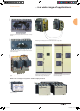
Low Voltage << Back Source changeover systems Compact, Interpact and Masterpact Catalogue 2008 312E0100.
PB100839 To ensure a continuous supply of electrical power, certain installations are connected to two sources: b a normal source N b a replacement source R used to supply the installation when the normal source is unavailable. PB100840 Interlocking of two Interpact switch-disconnectors via rotary handles. A source-changeover system switches the load between these two sources. It can be automated to manage transfers according to external conditions.
Source-changeover systems General content Presentation 3 Functions and characteristics A-1 Dimensions B-1 Electrical diagrams C-1 Catalogue numbers and order forms D-1 Livre 1.
Presentation For maximum continuity of service ... 0 Manual source-changeover system PB103937 This is the most simple type. It is controlled manually by an operator and consequently the time required to switch from the normal to the replacement source can vary. A manual source-changeover system is made up of two or three mechanically interlocked manually-operated circuit breakers or switch-disconnectors.
... in a wide range of applications PB100839 PB100842 Presentation PB100840 Interlocking of two Interpact switch-disconnectors via rotary handles. PB100850 PB100849 Interlocking of two Masterpact NT and NW circuit breakers using cables. PB100957-62 Complete source-changeover assembly with two Interpact switch-disconnectors. Interlocking of two Masterpact NT or NW circuit breakers using connecting rods. Interlocking of two Compact NS circuit breakers on a base plate.
For maximum continuity of service... Presentation 0 DB101543 PB100853 Incoming feeders and main LV switchboards Currents From 630 to 6300 A. PB100852 Power distribution Currents From 250 to 3200 A. PB100854 Loads Currents From 40 to 400 A. Livre 1.
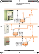
... in a wide range of applications Presentation 0 QN 0 1 0 QR QS1 0 0 1 2 normal sources 1 replacement source DB101540 DB101539 2 sources with coupler on busbars DB101538 1 normal source 1 replacement source QC QS2 0 0 0 1 0 1 1 1 0 0 1 1 1 0 0 (1) 0 0 1 (1) (1) possible by forcing operation.
TOOLS schneider-electric.com The technical guide This international site allows you to access all the Schneider Electric products in just clicks via comprehensive range datasheets, with direct links to: p complete library: technical documents, catalogs, FAQs, brochures… p selection guides from the e-catalog. p product discovery sites and their Flash animations.
Source-changeover systems Functions and characteristics Presentation Overview of solutions Manual source-changeover systems Interpact INS and Compact NS 40 A to 630 A Manual source-changeover systems Compact NS and Masterpact NT/NW 630 A to 6300 A Remote-operated source-changeover systems Compact NS100/1600 100 A to 1600 A Remote-operated source-changeover systems Masterpact NT/NW 630 A to 6300 A Manual source-changeover systems Possible combinations Remote-operated source-changeover systems Mechanical
Functions and characteristics Overview of solutions Range Interpact Rating (A) Type of device INS250 to INS630 INV250 to INV630 100 to 630 Switch-disconnectors NS100 to NS250 NS400 to NS630 100 to 630 N/H/L circuit breakers NA switch-disconnectors DB101548 Compact INS40 to INS80 INS100 to INS160 40 to 160 Switch-disconnectors with extended handles DB101547 Models Manual source-changeover systems Interpact INS and Compact NS 40 A to 630 A Manual source-changeover systems DB101545 DB101768 Int
Functions and characteristics Overview of solutions Range Compact Masterpact NS630b to NS1600 630 to 1600 N/H/L circuit breakers NA switch-disconnectors NT06 to NT16 630 to 1600 H1/L1 circuit breakers HA switch-disconnectors Models Rating (A) Type of device Manual source-changeover systems Compact NS and Masterpact NT/NW 630 A to 6300 A NW08 to NW63 800 to 6300 N1/H1/H2/H3/L1 circuit breakers NA/HA/HF switchdisconnectors Manual source-changeover systems DB101553 DB101769 Interlocking via extende
Functions and characteristics Overview of solutions Range Compact Models Rating (A) Type of device Remote-operated source-changeover systems Compact NS100/1600 100 A to 1600 A NS100 to NS630 100 to 630 N/H/L circuit breakers NA switch-disconnectors NS630b to NS1600 630 to 1600 N/H/L circuit breakers NA switch-disconnectors Remote-operated source-changeover system DB101563 DB101771 Mechanical interlocking on base plate + electrical interlocking 2 electrically-operated devices side-by-side combined
Functions and characteristics Overview of solutions Range Masterpact Models Rating (A) Type of device Remote-operated source-changeover systems Masterpact NT/NW 630 A to 6300 A NT06 to NT16 630 to 1600 H1/L1 circuit breakers HA switch-disconnectors NW08 to NW63 800 to 6300 N1/H1/H2/H3/L1 circuit breakers NA/HA/HF switch-disconnectors Remote-operated source-changeover system DB101559 DB101558 DB101773 Mechanical interlocking using connecting rods + electrical interlocking 2 electrically-operated
Manual source-changeover systems Functions and characteristics Possible combinations A manual source-changeover system can be installed on two or three manually-operated and mechanically interlocked circuit breakers or switch-disconnectors. Interlocks prevent connection to both sources at the same time, even momentarily.
Manual source-changeover systems Functions and characteristics Possible combinations All possibilities for manual source-changeover systems DB101571 Complete source-changeover assembly for two switchdisconnectors These assemblies provide an easy way to implement source changeover functions with: b a single 3-position rotary handle that controls the two switch-disconnectors (Normal source ON, OFF, Replacement source ON) b a smaller size, taking up less room in the switchboard.
Manual source-changeover systems Functions and characteristics Possible combinations Combination of “Normal” and “Replacement” devices All Interpact, Compact and Masterpact circuit breakers and switch-disconnectors from 100 to 6300 A with rotary handles or motor mechanisms can be interlocked. DB101569 Interlocking of a number of devices using keylocks (captive keys) Interlocking is based on two identical keylocks with a single key and a keylock adapter (different for each device).
Manual source-changeover systems Functions and characteristics Possible combinations Possible combinations of “Normal” and “Replacement” source switch-disconnectors Interlocking of two devices with rotary handles DB107742 The direct or extended rotary handles are padlocked with the devices in the OFF position. The mechanism prevents simultaneous closing of the devices, but allows them to be opened.
Functions and characteristics Remote-operated source-changeover systems Mechanical interlocking PB100930-67 Electrical interlocking of two or three devices is used to create a remote-operated source-changeover system. A basic mechanical interlocking system enhances the reliability of system operation. Interlocking of two Compact NS100 to 630 devices using a base plate A base plate designed for two Compact circuit breakers can be installed horizontally or vertically on a mounting rail.
Functions and characteristics Remote-operated source-changeover systems Mechanical interlocking PB100842 Interlocking of two Compact NS630b to 1600 or two Masterpact NT/NW or up to three Masterpact NW devices using cables For cable interlocking, the circuit breakers may be mounted one above the other or side-by-side. The interlocked devices may be fixed or drawout, three-pole or four-pole, and have different ratings and sizes.
Remote-operated source-changeover systems Functions and characteristics 0 General characteristics Range Compact Types of devices Types of circuit breakers Switch-disconnector version Mixing possibilities Electrical characteristics Rating Insulating voltage Ui (V AC) Positive break indication Number of poles (N and R devices must have the same number of poles) Electrical durability Operating temperature Control characteristics Control voltage Maximum consumption NS100 to NS250 N/H/L NA all devices NS
Functions and characteristics Remote-operated source-changeover systems General characteristics Masterpact NS630b to NS1600 N/H/L NA all devices NS630b to 1600 N/H/L/NA fixed or plug-in NT06 to 16 N1 / H1 / H2 / H3 / L1 NA / HA / HF all mixing possibilities (fixed, drawout or fixed + drawout) N1/H1/H2/H3/L1/NA/HA/HF NW08 to 63 N1 / H1 / H2 / H3 / L1 NA / HA / HF all mixing possibilities (fixed, drawout or fixed + drawout) N1/H1/H2/H3/L1/NA/HA/HF 250 to 1600 A 750 600 to 1600 A 1000 b 3, 4 800 to 6300
Remote-operated source-changeover systems Functions and characteristics Mechanical and electrical durability Interpact INS switch-disconnectors INS250-100 INS250-160 INS250-200 Number of poles Conventional thermal current (A) Rated operational current (A) lth Ie Durability (category A) (ON-CR-OR-CN cycles) Number of poles Conventional thermal current (A) Rated operational current (A) Durability (category A) (ON-CR-OR-CN cycles) lth Ie At 60 °C Electrical AC, 50/60 Hz 440-480 V 660-690 V Mechanical E
Functions and characteristics Remote-operated Connection and insulation accessories for Compact NS and INS y 630 A DB101605 Downstream coupling accessory This accessory simplifies connection to bars and cables with lugs. It may be used to couple two circuit breakers (Compact NS100 to 630) or switchdisconnectors (Interpact INS/INV100 to 630) of the same size. Pitch between outgoing terminals: b Interpact INS250 and INV100 to 250: 35 mm b Interpact INS/INV320 to 630: 52.
Remote-operated source-changeover systems Functions and characteristics Electrical interlocking Electrical interlocking is used with the mechanical interlocking system. It electrically interlocks the two circuit breakers and implements the time delays required for proper operation of the system. An automatic controller may be added to take into account information from the distribution system. Electrical interlocking is carried out by an electrical control device.
Functions and characteristics Remote-operated source-changeover systems Standard configurations Compact NS, Masterpact NT and NW Types of mechanical interlocking Possible combinations Typical electrical diagrams Diagram no.
Functions and characteristics By combining a remote-operated source-changeover system with an integrated BA or UA automatic controller, it is possible to automatically control source transfer according to userselected sequences. These controllers can be used on source-changeover systems comprising 2 circuit breakers.
Associated controllers Functions and characteristics Controller installation ACP auxiliaries control plate PB100857 The auxiliaries control plate provides in a single unit: b protection for the BA or UA controller with two highly limiting P25M circuit breakers (infinite breaking capacity) for power drawn from the AC source b control of circuit-breaker ON and OFF functions via two relay contactors b connection of the circuit breakers to the BA or UA controller via a built-in terminal block.
Functions and characteristics Associated controllers The BA controller is used to create simple sourcechangeover systems that switch from one source to another depending on the presence of voltage UN on the “Normal” source. It is generally used to manage two permanent sources and can control Compact NS and Masterpact NT/NW circuit breakers and switch-disconnectors.
Functions and characteristics Associated controllers BA controller operating sequences Switch set to the “N” position (forced operation on the “Normal” source) DB101584 DB101582 Switch set to Auto (automatic operation and special-tariff mode) 1 Switch set to the “Stop” position DB101588 DB101586 Switch set to the “R” position (forced operation on the “Replacement” source) Key UN : “Normal” source voltage UR : “Replacement” source voltage N : “Normal” source circuit breaker R : “Replacement” source
Associated controllers The UA controller is used to create a sourcechangeover system integrating the following automatic functions: b transfer from one source to another depending on the presence of voltage UN on the “Normal” source b startup of an engine generator set b shedding and reconnection of non-priority circuits b transfer to the “Replacement” source if one of the phases on the “Normal” source fails. The UA controller can control Compact NS and Masterpact NT/NW devices.
Functions and characteristics Associated controllers UA controller operating sequences Switch set to the “N” position (forced operation on the “Normal” source) DB101590 DB101592 Switch set to the “R” position (forced operation on the “Replacement” source) DB101594 Switch set to the “Stop” position WAITING The system exits this mode when the operating mode is modified or when an external event occurs (e.g. failure or return of UN).
Functions and characteristics Associated controllers UA controller Operating sequences DB117634 Switch set to the “Auto” position (special-tariff mode) WAITING The system exits this mode when the operating mode is modified or when an external event occurs (e.g. failure or return of UN). When the UA controller is not energised, the output for generator set startup is activated).
Functions and characteristics Associated controllers UA controller Operating sequences DB101598 Switch set to the “Auto” position (automatic operation and test mode). WAITING The system exits this mode when the operating mode is modified or when an external event occurs (e.g. failure or return of UN). When the UA controller is not energised, the output for generator set startup is activated).
Functions and characteristics Operating sequences DB101600 IVE unit Symbols QN : “Normal” Compact C circuit breaker equipped for remote operation (motor mechanism) QR : “Replacement” Compact C circuit breaker equipped for remote operation (motor mechanism) ON : Circuit breaker QN opening order OR : Circuit breaker QR opening order IN : Circuit breaker QN closing order IR : Circuit breaker QR closing order L1 : Faulty “Normal” indication LED L2 : Faulty “Replacement” indication LED Key O: OFF (
Functions and characteristics Operating sequences DB101602 BA controller Inputs UN : “Normal” source voltage UR : “Replacement” source voltage KT : order for forced-operation on R KR : additional check before transfer Outputs QN : “Normal” source circuit breaker QR : “Replacement” source circuit breaker DB101604 UA controller Inputs UN : “Normal” source voltage UR : “Replacement” source voltage KT : order for forced-operation on R KR : additional check before transfer Outputs KG : order to the genset
Functions and characteristics COM communications option DB101928 Communications option for Compact NS and Masterpact NT/NW The COM communications option is compatible with all the source-changeover systems for Compact NS100 to 1600 and Masterpact NT/NW circuit breakers and switch-disconnectors. It can be used to remote status information. It may not be used to operate the circuit breakers (only possible locally on the front of the UA150 controller).
Functions and characteristics COM communications option Automatic source-changeover controller UA150 Status indications “Normal” source ON / OFF Circuit breaker ON Fault trip (SDE) Voltage presence “Replacement” source Circuit breaker ON Fault trip (SDE) Voltage presence Status of R voltage contact Controller Automatic mode “Normal” mode “Replacement” mode Stop mode Testing “Replacement” engine generator set Genset failure Genset OFF Genset ON Shedding of non-priority circuits Reconnection of non-priorit
TOOLS schneider-electric.com CAD software and tools This international site allows you to access all the Schneider Electric products in just clicks via comprehensive range datasheets, with direct links to: p complete library: technical documents, catalogs, FAQs, brochures… p selection guides from the e-catalog. p product discovery sites and their Flash animations.
Source-changeover systems Dimensions Presentation Functions and characteristics 2 A-1 Manual source-changeover systems B-2 Remote-operated source-changeover systems B-9 Interlocking of direct rotary handles Interlocking of extended rotary handles Interlocking of toggles Complete source-changeover assembly Downstream coupling accessory Interlocking on a base plate Interlocking using connecting rods Interlocking using cables IVE electrical-interlocking unit BA and UA automatic controllers Electrical
Manual source-changeover systems Dimensions Interlocking of direct rotary handles Compact NS100 to 1600 DB101608 Front-panel cutout DB101607 DB101606 Dimensions Dimensions (mm) Type NS100/160/250N/H/L NS400/630N/H/L A 325 416 B 90 115 C 87.5 100 D 175 200 F 156 210 G 133 157 H 9.25 5 J 9 24.6 K 295 386 L 75.5 100 M 150 175 N 75 74.
Manual source-changeover systems Dimensions Interlocking of extended rotary handles Compact NS100 to 630 DB107757 Front-panel cutout DB101607 DB101612 Dimensions Dimensions (mm) Type NS100/160/250N/H/L NS400/630N/H/L A 325 416 B 90 115 C 87.5 100 D 175 200 F 156 210 G min 185 204 G max 600 600 H 9.25 5 J 9 24.6 P 25.5 30.8 Q 25.5 30.
Manual source-changeover systems Dimensions Interlocking of extended rotary handles Compact NS630b to 1600 DB101618 DB101617 Dimensions DB101619 Front-panel cutout Dimensions (mm) Type NS630b/800/1000/1200/1600 A 411 B 63.5 C 98 D 175 F 280 G min 218 G max 605 H 25 J 24 P 25.5 Q 25.5 R 64 B-4 Livre 1.
Manual source-changeover systems Dimensions Interlocking of toggles Compact NS100 to 630 4 poles 4 poles on left DB101623 3 poles on left DB101624 DB101620 Front-panel cutout DB101622 3 poles DB101621 Dimensions Dimensions (mm) Type NS100/160/250N/H/L NS400/630N/H/L C2 54 92.5 C3 108 184 L 52.5 70 L16 140 185 L17 245 325 L18 280 370 R2 54 71.5 R18 89 116.5 R19 140 185 P5 83 107 P 115 144 B-5 Livre 1.
Manual source-changeover systems Dimensions Complete source-changeover assembly Assembly for INS250 100 to 250 A / Assembly for INS320/400/500/630 DB101626 DB101625 Dimensions DB101627 Front-panel cutout Dimensions (mm) Type INS250 INS320/630 A 60.4 82.5 B 130.4 175 C 296 395 D 68 102.5 E 136 205 F 131 155 G 61.8 87 H 279.3 383.7 I 42 64 J 84 128 K 156 210 L 186.5 213 M 5.
Manual source-changeover systems Dimensions Downstream coupling accessory Compact NS100 to NS630 (only for Compact NS fixed devices) DB101629 DB101628 Dimensions Connection DB101630 DB101631 Dimensions Dimensions (mm) Type NS100/160/250 NS400/630 G2 118 165.9 G3 181.5 265.7 G28 238 339.5 G29 96 143.5 G30 140 188.5 G52 156 227.5 K1 35 45 K2 35 52.5 K3 51 75 K4 156 210 K8 70 113.5 K9 170 250.7 K16 8 3.75 L28 320 420 L29 99.5 127.5 L30 300 400 L31 89.5 117.5 L32 1 11.2 L33 123 187.
Manual source-changeover systems Dimensions Downstream coupling accessory Interpact INS250 100 to 250 A / Interpact INS320/400/500/630 DB101633 DB101632 Dimensions DB101902 Connection DB101901 Dimensions Dimensions (mm) Type INS250-100/160/200/250 INS320/400/500/630 G2 105.5 141 G3 169 240.7 G28 225.5 315 G29 83.5 119 G30 127.5 163.5 G52 143.5 202.5 K1 35 45 K2 35 52.5 K3 51 75 K4 156 210 K8 57.5 88.5 K9 157.5 225.7 K16 25.5 26.
Remote-operated source-changeover systems Dimensions Interlocking on a base plate Compact NS100 to 250 DB101636 Withdrawable device DB101635 Fixed device DB101634 Dimensions, 3 or 4 poles (*) Short terminal shields are mandatory. DB101638 Horizontal mounting DB101637 Vertical mounting Dimensions (mm) Type NS100/160/250N/H/L NS400/630N/H/L G50 137.5 180 G51 285 360 H20 62.5 100 H21 97 152 H22 45.5 83 H23 73 123 H42 60 60 H43 120 120 H44 144.
Remote-operated source-changeover systems Dimensions Interlocking on a base plate Compact NS400 to 630 DB101640 Fixed device DB101639 Dimensions, 3 or 4 poles DB101641 Withdrawable device Note: coupling accessory: only for changeover systems using fixed versions of Compact NS circuit breakers. Horizontal mounting DB101638 DB101637 Dimensions Vertical mounting (*) Short terminal shields are mandatory. Note: dimensions see p. B-9. B-10 Livre 1.
Remote-operated source-changeover systems Dimensions Interlocking on a base plate “Normal” and “Replacement” source devices: NS100 to NS250 Front-panel cutout DB107744 DB101642 Dimensions “Normal” and “Replacement” source devices: NS400 to NS630 Front-panel cutout DB107745 DB101644 Dimensions Note for Compact NS: For dimensions with the accessories (IP40 escutcheons and Vigi escutcheon protection collars), see Catalogue Compact. B-11 Livre 1.
Remote-operated source-changeover systems Dimensions Interlocking on a base plate NS400 to NS630 as the “Normal” device, NS100 to NS250 as the “Replacement” device Front-panel cutout DB107746 DB101646 Dimensions B-12 Livre 1.
Dimensions Remote-operated source-changeover systems Interlocking using connecting rods Two Compact NS630b to NS1600 devices one above the other Withdrawable devices DB101655 DB107747 Fixed devices Two Masterpact NT devices one above the other Withdrawable devices DB101655 DB101656 Fixed devices B-13 Livre 1.
Dimensions Remote-operated source-changeover systems Interlocking using connecting rods Two Masterpact NW devices one above the other Withdrawable devices DB107749 DB107748 Fixed devices B-14 Livre 1.
Dimensions Remote-operated source-changeover systems Interlocking using cables Two Compact NS630b to NS1600 devices side-by-side Withdrawable devices DB101662 DB101661 Fixed devices Two Masterpact NT devices side-by-side Drawout devices DB101663 DB101662 Fixed devices Combination of two Masterpact NT and NW devices side-by-side Drawout devices DB101665 DB101664 Fixed devices B-15 Livre 1.
Dimensions Remote-operated source-changeover systems Interlocking using cables Two Masterpact NW devices side-by-side Drawout devices DB101667 DB101666 Fixed devices Three Masterpact NW devices side-by-side DB101668 Fixed devices DB101669 Drawout devices B-16 Livre 1.
Dimensions Remote-operated source-changeover systems Interlocking using cables Two Compact NS630b to NS1600 devices one above the other Withdrawable devices DB107750 DB101671 Fixed devices Two Masterpact NT devices one above the other Drawout devices DB101671 DB101672 Fixed devices B-17 Livre 1.
Dimensions Remote-operated source-changeover systems Interlocking using cables Two Masterpact NW devices one above the other Drawout devices DB107752 DB107751 Fixed devices Two Masterpact NT and NW devices one above the other Drawout devices DB107752 DB107753 Fixed devices B-18 Livre 1.
Dimensions Remote-operated source-changeover systems Interlocking using cables Three Masterpact NW devices one above the other Drawout devices DB107755 DB107754 Fixed devices B-19 Livre 1.
Remote-operated source-changeover systems Dimensions IVE electrical-interlocking unit BA and UA automatic controllers DB101678 Door cutout for BA/UA controllers DB101682 DB101680 DB101681 ACP auxiliaries control plate and BA/UA controller DB101683 DB101679 IVE electrical-interlocking unit (1) Cutout according DIN 43700 standard. B-20 Livre 1.
B-21 Livre 1.
TOOLS schneider-electric.com Training This international site allows you to access all the Schneider Electric products in just clicks via comprehensive range datasheets, with direct links to: p complete library: technical documents, catalogs, FAQs, brochures… p selection guides from the e-catalog. p product discovery sites and their Flash animations.
Source-changeover systems Electrical diagrams Presentation Functions and characteristics Dimensions 2 A-1 B-1 Remote-operated source-changeover systems C-2 2 Compact NS100/1600 or Masterpact NT/NW devices 2 Compact NS100/630 devices 2 Compact NS630b/1600 devices 2 Masterpact NT or NW devices 3 Masterpact NW devices C-2 C-3 C-6 C-14 C-24 Source-changeover systems with automatic controllers 2 Compact NS100/1600 or Masterpact NT/NW devices 2 Masterpact NT or NW devices Catalogue numbers and order forms
Electrical diagrams Remote-operated source-changeover systems 2 Compact NS100/1600 or Masterpact NT/NW devices Electrical interlocking by the IVE unit DB101689 Recommended electrical control system (1) The “normal” and “replacement” source transfer orders must be interlocked electrically. (2) Operating diagram: the SDE “fault-trip” signals are transmitted to the IVE unit. The SDE auxiliary contacts are mounted in the circuit breakers.
Electrical diagrams Remote-operated source-changeover systems 2 Compact NS100/630 devices Diagram no. 51201177 Source-changeover system without automatic-control system Local reset DB101659 DB101686 Without auxiliaries for emergency off DB101660 Voluntary remote reset Automatic reset ATTENTION (1) Prefabricated wiring: cannot be modified. The diagram shows the electrical wiring for circuit breakers. When wiring the SDE with switch-disconnectors, reverse the wires connected to terminals 82 and 84.
Electrical diagrams Remote-operated source-changeover systems 2 Compact NS100/630 devices Diagram no. 51201178 Source-changeover system without automatic-control system DB112553 With emergency off by MN release and automatic reset Automatic reset ATTENTION The diagram shows the electrical wiring for circuit breakers. When wiring the SDE with switch-disconnectors, reverse the wires connected to terminals 82 and 84.
Electrical diagrams Remote-operated source-changeover systems 2 Compact NS100/630 devices Diagram no. 51201179 Source-changeover system without automatic-control system DB101691 With emergency off by MX release and automatic reset Automatic reset ATTENTION The diagram shows the electrical wiring for circuit breakers. When wiring the SDE with switch-disconnectors, reverse the wires connected to terminals 82 and 84.
Electrical diagrams Remote-operated source-changeover systems 2 Compact NS630b/1600 devices Diagram no. 51201180 DB101693 Electrical interlocking ATTENTION (1) Not to be wired on fixed version. The diagram shows the electrical wiring for circuit breakers. When wiring the SDE with switch-disconnectors, connect the SDE to terminals 81 and 84. States permitted by mechanical interlocking system Legends QN “Normal” source Compact NS630b to 1600 QR “Replacement” source Compact NS NS630b to 1600 OF...
Electrical diagrams Remote-operated source-changeover systems 2 Compact NS630b/1600 devices Diagram no. 51201181 DB101695 Electrical interlocking with emergency off by shunt release ATTENTION (1) Not to be wired on fixed version. The diagram shows the electrical wiring for circuit breakers. When wiring the SDE with switch-disconnectors, connect the SDE to terminals 81 and 84. Legends QN “Normal” source Compact NS630b to 1600 QR “Replacement” source Compact NS NS630b to 1600 OF...
Remote-operated source-changeover systems Electrical diagrams 2 Compact NS630b/1600 devices Diagram no. 51201182 DB101697 Electrical interlocking with emergency off by undervoltage (1) Not to be wired on fixed version. ATTENTION The diagram shows the electrical wiring for circuit breakers. When wiring the SDE with switch-disconnectors, connect the SDE to terminals 81 and 84. Legends QN “Normal” source Compact NS630b to 1600 QR “Replacement” source Compact NS NS630b to 1600 OF...
Remote-operated source-changeover systems Electrical diagrams 2 Compact NS630b/1600 devices Diagram no. 51201183 DB112554 Electrical interlocking by IVE ATTENTION The diagram shows the electrical wiring for circuit breakers. When wiring the SDE with switch-disconnectors, connect wire BK to terminal 82. Legends QN “Normal” source Compact NS630b to 1600 QR “Replacement” source Compact NS NS630b to 1600 OF...
Remote-operated source-changeover systems Electrical diagrams 2 Compact NS630b/1600 devices Diagram no. 51201184 DB112555 Electrical interlocking by IVE with emergency off by shunt release ATTENTION The diagram shows the electrical wiring for circuit breakers. When wiring the SDE with switch-disconnectors, connect wire BK to terminal 82. Legends QN “Normal” source Compact NS630b to 1600 QR “Replacement” source Compact NS NS630b to 1600 OF...
Remote-operated source-changeover systems Electrical diagrams 2 Compact NS630b/1600 devices Diagram no. 51201185 DB112556 Electrical interlocking by IVE with emergency off by undervoltage release ATTENTION The diagram shows the electrical wiring for circuit breakers. When wiring the SDE with switch-disconnectors, connect wire BK to terminal 82.
Electrical diagrams Remote-operated source-changeover systems 0 2 Compact NS630b/1600 devices Diagram no. 51201186 DB101705 Automatic-control system without IVE for permanent replacement source ATTENTION (1) Not to be wired on fixed version. The diagram shows the electrical wiring for circuit breakers. When wiring the SDE with switch-disconnectors, connect the SDE to terminals 81 and 84. Legends QN Normal” source Compact NS630b to 1600 QR “Replacement” source Compact NS NS630b to 1600 OF...
Remote-operated source-changeover systems Electrical diagrams 2 Compact NS630b/1600 devices Diagram no. 51201187 DB101707 Automatic-control system for replacement source generator set (1) Not to be wired on fixed version. ATTENTION The diagram shows the electrical wiring for circuit breakers. When wiring the SDE with switch-disconnectors, connect the SDE to terminals 81 and 84. Legends QN “Normal” source Compact NS630b to 1600 QR “Replacement” source Compact NS NS630b to 1600 OF...
Electrical diagrams Remote-operated source-changeover systems 2 Masterpact NT or NW devices Diagram no. 51201139 DB101709 Electrical interlocking with lockout after a fault ATTENTION (1) Not to be wired on fixed version. The diagram shows the electrical wiring for circuit breakers. When wiring the SDE with switch-disconnectors, connect the SDE to terminals 81 and 84.
Electrical diagrams Remote-operated source-changeover systems 2 Masterpact NT or NW devices Diagram no. 51201140 DB101711 Electrical interlocking with lockout after a fault and emergency off by shunt release ATTENTION (1) Not to be wired on fixed version. The diagram shows the electrical wiring for circuit breakers. When wiring the SDE with switch-disconnectors, connect the SDE to terminals 81 and 84.
Electrical diagrams Remote-operated source-changeover systems 0 2 Masterpact NT or NW devices Diagram no. 51201141 DB101713 Electrical interlocking with lockout after a fault and emergency off by undervoltage release ATTENTION (1) Not to be wired on fixed version. The diagram shows the electrical wiring for circuit breakers. When wiring the SDE with switch-disconnectors, connect the SDE to terminals 81 and 84.
Remote-operated source-changeover systems Electrical diagrams 2 Masterpact NT or NW devices Diagram no. 51201142 DB101715 Electrical interlocking by IVE with lockout after a fault ATTENTION The diagram shows the electrical wiring for circuit breakers. When wiring the SDE with switch-disconnectors, connect wire BK to terminal 82.
Remote-operated source-changeover systems Electrical diagrams 0= 2 Masterpact NT or NW devices Diagram no. 51201143 DB101717 Electrical interlocking by IVE with lockout after a fault and emergency off by shunt release ATTENTION The diagram shows the electrical wiring for circuit breakers. When wiring the SDE with switch-disconnectors, connect wire BK to terminal 82.
Remote-operated source-changeover systems Electrical diagrams 2 Masterpact NT or NW devices Diagram no. 51201144 DB101719 Electrical interlocking by IVE with lockout after a fault and emergency off by undervoltage release ATTENTION The diagram shows the electrical wiring for circuit breakers. When wiring the SDE with switch-disconnectors, connect wire BK to terminal 82.
Electrical diagrams Remote-operated source-changeover systems 2 Masterpact NT or NW devices Diagram no. 51156226 DB101721 Automatic-control system without IVE for permanent replacement source with lockout after a fault ATTENTION (1) Not to be wired on fixed version. The diagram shows the electrical wiring for circuit breakers. When wiring the SDE with switch-disconnectors, connect the SDE to terminals 81 and 84.
Electrical diagrams Remote-operated source-changeover systems 2 Masterpact NT or NW devices Diagram no. 51156227 DB101723 Automatic-control system for replacement source generator set with lockout after a fault ATTENTION (1) Not to be wired on fixed version. The diagram shows the electrical wiring for circuit breakers. When wiring the SDE with switch-disconnectors, connect the SDE to terminals 81 and 84.
Remote-operated source-changeover systems Electrical diagrams 2 Masterpact NT or NW devices Diagram no. 51156904 DB112557 Automatic-control system for permanent replacement source with lockout after a fault (with MN) ATTENTION The diagram shows the electrical wiring for circuit breakers. When wiring the SDE with switch-disconnectors, connect wire BK to terminal 82.
Remote-operated source-changeover systems Electrical diagrams 2 Masterpact NT or NW devices Diagram no. 51156905 DB112558 Automatic-control system for replacement source generator set with lockout after a fault (with MN) ATTENTION The diagram shows the electrical wiring for circuit breakers. When wiring the SDE with switch-disconnectors, connect wire BK to terminal 82.
Electrical diagrams Remote-operated source-changeover systems 3 Masterpact NW devices Diagram no. 51156906 DB101734 2 Normal sources and 1 Replacement source: electrical interlocking without lockout after a fault Legends QN... “Normal” source Masterpact NW QR “Replacement” source Masterpact NW MCH spring-charging motor MX standard opening voltage release XF standard closing voltage release OF...
Electrical diagrams Remote-operated source-changeover systems 3 Masterpact NW devices Diagram no. 51156907 DB101766 2 Normal sources and 1 Replacement source: electrical interlocking with lockout after a fault ATTENTION The diagram shows the electrical wiring for circuit breakers. When wiring the SDE with switch-disconnectors, connect the SDE to terminals 81 and 84. Legends QN...
Electrical diagrams Remote-operated source-changeover systems 3 Masterpact NW devices Diagram no. 51156908 DB101737 2 Normal sources and 1 Replacement source: automatic-control system for generator set without lockout after a fault (with MN) Legends QN... “Normal” source Masterpact NW QR “Replacement” source Masterpact NW MCH spring-charging motor XF standard closing voltage release undervoltage release MN OF... breaker ON/OFF indication contact PF “ready-to-close” contact CE...
Electrical diagrams Remote-operated source-changeover systems 3 Masterpact NW devices Diagram no. 51156909 DB101739 2 Normal sources and 1 Replacement source: automatic-control system for generator set with lockout after a fault (with MN) ATTENTION The diagram shows the electrical wiring for circuit breakers. When wiring the SDE with switch-disconnectors, connect the SDE to terminals 81 and 84. Legends QN...
Electrical diagrams Remote-operated source-changeover systems 3 Masterpact NW devices Diagram no. 51156910 DB101741 3 sources with only 1 device closed: electrical interlocking without lockout after a fault Legends QS... “Source” Masterpact NW MCH spring-charging motor MX standard opening voltage release XF standard closing voltage release OF... breaker ON/OFF indication contact PF “ready-to-close” contact CE...
Electrical diagrams Remote-operated source-changeover systems 3 Masterpact NW devices Diagram no. 51156911 DB101743 3 sources with only 1 device closed: electrical interlocking with lockout after a fault ATTENTION The diagram shows the electrical wiring for circuit breakers. When wiring the SDE with switch-disconnectors, connect the SDE to terminals 81 and 84. Legends QS... “Source” Masterpact NW MCH spring-charging motor MX standard opening voltage release standard closing voltage release XF OF...
Electrical diagrams Remote-operated source-changeover systems 3 Masterpact NW devices Diagram no. 51156912 DB101745 2 sources and 1 coupling: electrical interlocking without lockout after a fault Legends QS... “Source” Masterpact NW QC “Coupling” Masterpact NW MCH spring-charging motor MX standard opening voltage release XF standard closing voltage release OF... breaker ON/OFF indication contact PF “ready-to-close” contact CE...
Electrical diagrams Remote-operated source-changeover systems 3 Masterpact NW devices Diagram no. 51156913 DB101747 2 sources and 1 coupling: electrical interlocking with lockout after a fault ATTENTION The diagram shows the electrical wiring for circuit breakers. When wiring the SDE with switch-disconnectors, connect the SDE to terminals 81 and 84. Legends QS...
Electrical diagrams Remote-operated source-changeover systems 3 Masterpact NW devices Diagram no. 51156914 DB101749 2 sources and 1 coupling: automatic-control system with lockout after a fault ATTENTION The diagram shows the electrical wiring for circuit breakers. When wiring the SDE with switch-disconnectors, connect the SDE to terminals 81 and 84. Legends QS...
Electrical diagrams Source-changeover systems with automatic controllers 2 Compact NS100/1600 or Masterpact NT/NW devices Source-changeover system with BA controller DB101753 DB101751 Coupling DB101755 Transfer conditions Terminals 20 and 21: additional control contact (not part of controller). Tests on “Normal” and “Replacement” source voltages The single-phase check for UN and UR is implemented across terminals 1 and 5 of circuit breakers Q1 and Q2.
Electrical diagrams Source-changeover systems with automatic controllers 2 Compact NS100/1600 or Masterpact NT/NW devices Source-changeover system with UA controller DB101758 DB101757 Load shedding and genset management DB101759 Transfer conditions Terminals 20 and 21: additional control contact (not part of controller).
Source-changeover systems with automatic controllers Electrical diagrams 2 Compact NS100/1600 or Masterpact NT/NW devices Using communication functions DB101763 DB101762 Controller settings Tests on “Normal” source voltage A = 0 single-phase test, A = 1 three-phase test. The address of the UA controller is set using the two BBus dials. Voluntary transfert (e.g. for energy management) b action in the event of genset failure B = 0 circuit breaker N opens, B = 1 circuit breaker N remains closed.
Source-changeover systems with automatic controllers Electrical diagrams 2 Masterpact NT or NW devices Diagram no. 51156903 DB101765 Electrical interlocking with lockout after a fault ATTENTION The diagram shows the electrical wiring for circuit breakers. When wiring the SDE with switch-disconnectors, connect wire BK to terminal 82.
C-37 Livre 1.
TOOLS schneider-electric.com The electrical installation guide This international site allows you to access all the Schneider Electric products in just clicks via comprehensive range datasheets, with direct links to: p complete library: technical documents, catalogs, FAQs, brochures… p selection guides from the e-catalog. p product discovery sites and their Flash animations.
Source-changeover systems Catalogue numbers and order forms Presentation Functions and characteristics Dimensions Electrical diagrams Source-changeover systems for 2 devices Interpact INS40 to INS2500 and INV100 to INV2500 Compact NS100 to NS630 Compact NS630b to NS1600 circuit breakers and switch-disconnectors Masterpact NT circuit breakers and switch-disconnectors Source-changeover systems for 2 or 3 devices Masterpact NW circuit breakers and switch-disconnectors Source-changeover systems for 2 devic
Catalogue numbers and order forms Source-changeover systems for 2 devices Interpact INS40 to INS2500 and INV100 to INV2500 Manual source-changeover systems Interpact INS40 to INS630 and INV100 to INV630 Interlocking for rotary handle 3/4P 28953 E89624 DB107710 Mechanical device for INS40 to INS160 equipped with an extended rotary handle ¿5...
Source-changeover systems for 2 devices (cont.) Catalogue numbers and order forms Compact NS100 to NS630 Manual source changeover Mechanical interlocking NS100...250 NS400...630 29354 32614 For rotary handled circuit breakers NS100...250 NS400...630 29369 32621 E18780 E21288 For toggle controlled circuit breakers Key lock interlocking E23851 For rotary handled or remote controlled circuit breakers 2 locks, 1 key Ronis 1351B.
Catalogue numbers and order forms Source-changeover systems for 2 devices (cont.) Compact NS100 to NS630 (cont.) Connection accessories Downstream coupling accessories 4P 29322 32563 250 A 29358 29359 630 A 32619 32620 NS100...250/NS100...250 NS400...630/NS400...630 Source “normal”/source “replacement” NS100...250/ NS100...250 NS400...630/ NS400...630 DB101062 E50998 3P 29321 32562 Short terminal shields (1 pair) DB101063 Long terminal shields (1 pair) NS100...250/NS100...250 NS400...
Catalogue numbers and order forms Source-changeover systems for 2 devices (cont.
Catalogue numbers and order forms Source-changeover systems for 2 devices (cont.) Compact NS630b to NS1600 circuit breakers and switch-disconnectors (cont.) Associated controller The automatic-control option includes: b an IVE electrical-interlocking unit b an ACP auxiliaries control plate b a BA or UA controller, depending on the required functions b a UA/BA adapter kit.
Catalogue numbers and order forms Source-changeover systems for 2 devices (cont.
Catalogue numbers and order forms Source-changeover systems for 2 or 3 devices Masterpact NW circuit breakers and switch-disconnectors Interlocking for source-changeover systems for 2 devices Interlocking of 2 devices using connecting rods E47762 Complete assembly with 2 adaptation fixtures + rods 2 Masterpact NW fixed devices 2 Masterpact NW drawout devices Can be used with 1 NW fixed + 1 NW drawout.
D-9 Livre 1.
Catalogue numbers and order forms Source-changeover systems for 2 devices Interpact INS40 to INS630 Switch-disconnectors To indicate your choices, check the applicable square boxes appropriate information in the rectangles .
Source-changeover systems for 2 devices Catalogue numbers and order forms Interpact INS40 to INS630 Switch-disconnectors To indicate your choices, check the applicable square boxes and enter the appropriate information in the rectangles .
Catalogue numbers and order forms Source-changeover systems for 2 devices Compact NS100 to NS630 / Circuit breakers and switch-disconnectors To indicate your choices, check the applicable square boxes appropriate information in the rectangles . and enter the Diagram for two Compact NS devices Without automatic control, without emergency off auxiliaries Without automatic control, with emergency off by MN Without automatic control, with emergency off by MX (no. 51201177) (no. 51201178) (no.
Source-changeover systems for 2 devices Catalogue numbers and order forms Compact NS100 to NS630 / Circuit breakers and switch-disconnectors To indicate your choices, check the applicable square boxes and enter the appropriate information in the rectangles .
Catalogue numbers and order forms Source-changeover systems for 2 devices Compact NS630b to NS1600 / Circuit breakers and switch-disconnectors To indicate your choices, check the applicable square boxes appropriate information in the rectangles .
Source-changeover systems for 2 devices Catalogue numbers and order forms Compact NS630b to NS1600 / Circuit breakers and switch-disconnectors To indicate your choices, check the applicable square boxes and enter the appropriate information in the rectangles .
Catalogue numbers and order forms Source-changeover systems for 2 devices Masterpact NT or NW / Circuit breakers and switch-disconnectors To indicate your choices, check the applicable square boxes appropriate information in the rectangles .
Source-changeover systems for 2 devices Catalogue numbers and order forms Masterpact NT or NW / Circuit breakers and switch-disconnectors To indicate your choices, check the applicable square boxes and enter the appropriate information in the .
Catalogue numbers and order forms Source-changeover systems for 3 devices Masterpact NW / Circuit breakers and switch-disconnectors To indicate your choices, check the applicable square boxes appropriate information in the rectangles . and enter the Diagram for 3 Masterpact NW devices 2 “Normal” sources + 1 “Replacement” source: Electrical interlocking without lockout after fault (no. 51156906) Electrical interlocking with lockout after fault (no.
Source-changeover systems for 3 devices Catalogue numbers and order forms Masterpact NW / Circuit breakers and switch-disconnectors To indicate your choices, check the applicable square and enter the appropriate information in the boxes .
Notes D-20 312E5100.
312E0100.
89, boulevard Franklin Roosevelt F - 92505 Rueil-Malmaison Cedex (France) Tel : +33 (0)1 41 29 85 00 As standards, specifications and designs change from time to time, please ask for confirmation of the information given in this publication. http://www.schneider-electric.com This document has been printed on ecological paper. Design: Schneider Electric Photos: Schneider Electric Printed: Centre Impression - made in France http://www.schneider-electric.co LVPED208007EN 312E0100.