
Installation guide


C-13
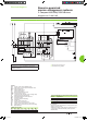
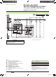
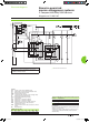
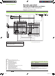
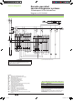
Electrical diagrams
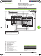
Automatic-control system for replacement source generator set
DB101707
ATTENTION
(1) Not to be wired on xed version.
The diagram shows the electrical wiring for circuit breakers.
When wiring the SDE with switch-disconnectors, connect
the SDE to terminals 81 and 84.
Legends
QN “Normal”
source Compact NS630b to 1600
QR “Replacement” source Compact NS NS630b to 1600
OF... breaker
ON/OFF indication contact
SDE1 “fault-trip”
indication contact
CE1 “connected-position” indication contact (carriage switch)
F1
auxiliary power supply circuit breaker
F2/F3 circuit
breaker (high breaking capacity)
S1 control
switches
KA1 auxiliary relays - UN presence detection
KA2 auxiliary
relays - UR presence detection
KA3 auxiliary relays - generator set startup if UN absent
KM1
contactors with 0.25 second delay (for transfer
to
“Replacement” source)
KM2 contactors with 0.25 second delay (for transfer to “Normal”
source)
MT Motor
Mechanism
States permitted by mechanical interlocking system
Normal Replacement
0 0
1 0
0 1
Note:
after a fault trip, the breaker must be reset manually by pressing
its reset button.
Diagram shown with circuit breakers in connected position, open,
charged, and ready to close.
Auxiliary power supply = supply voltage of auxiliary relays (KA...)
= supply voltage of electrical auxiliaries (electrical operation,
MCH, MX, MN...).
Wiring colour codes
RD GN BK VT YE GY WH BN
red green black violet yellow grey white brown
Remote-operated
source-changeover systems
2 Compact NS630b/1600 devices
Diagram no. 51201187
Livre 1.indb 13 08/10/2008 18:39:47