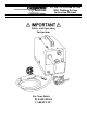
FP-120, FP-130 and FP-160 MIG Welding System Instruction Manual FORM NO. 0056-1842 EFFECTIVE July 2001 Safety and Operating Instructions For Your Safety . . .
Table of Contents page Introduction . . . . . . . . . . . . . . . . . . . . . . . . . . . . . . . . . . . . . . . . . . . . . . . . . . . . . . . . . . . . . . . . . . . . . . . . . . .1 Safety Profile . . . . . . . . . . . . . . . . . . . . . . . . . . . . . . . . . . . . . . . . . . . . . . . . . . . . . . . . . . . . . . . . . . . . . . . . . .1 Safety Information . . . . . . . . . . . . . . . . . . . . . . . . . . . . . . . . . . . . . . . . . . . . . . . . . . . . . . . . . . . . . . . . . . . . . .
page FP-120 Parts List . . . . . . . . . . . . . . . . . . . . . . . . . . . . . . . . . . . . . . . . . . . . . . . . . . . . . . . . . . . . . . . . . . . . . .20 FP-130 Parts List . . . . . . . . . . . . . . . . . . . . . . . . . . . . . . . . . . . . . . . . . . . . . . . . . . . . . . . . . . . . . . . . . . . . . .22 FP-160 Parts List . . . . . . . . . . . . . . . . . . . . . . . . . . . . . . . . . . . . . . . . . . . . . . . . . . . . . . . . . . . . . . . . . . . . . .
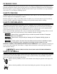
INTRODUCTION This User’s Guide provides specific information about your Firepower Welding System. This guide provides pertinent information needed to safely and effectively use your Firepower Welding System. The information in this manual applies to specific Firepower Welding System models. It gives instructions on set-up, installation and actual use of your Firepower Welding System. SAFETY PROFILE Tradesmen respect the tools and equipment with which they work.
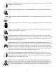
Indicates that the helmet must be worn during the step(s) that follow to protect against eye damage and burns due to flash hazard. Indicates that the possibility of toxic gas hazard exists during operation of the step(s) that follow. Indicates that the possibility of being burned by hot slag exists during operation of the step(s) that follow. Indicates that eye protection should be worn to protect against flying debris in the following step(s).
IMPROPER HANDLING AND MAINTENANCE OF COMPRESSED GAS CYLINDERS AND REGULATORS CAN RESULT IN SERIOUS INJURY OR DEATH! Reduce the risk of injury or death from compressed gasses and equipment hazards. Read, understand and follow the following safety instructions. Additionally, make certain that anyone else who uses this welding equipment, or who is a bystander in the welding area, understands and follows these safety instructions as well.
5. Remove all combustible materials from the work site. If you can not remove them, protect them with fireproof covers. NEVER perform welding operations on a container that has held toxic, combustible or flammable liquids or vapors. NEVER perform welding operations in an area containing combustible vapors, flammable liquids or explosive dust. VENTILATION Ventilate welding work areas adequately. Maintain sufficient air flow to prevent accumulation of explosive or toxic concentrations of gases.
HEALTH HAZARDS The welding process can be hazardous to your health. Therefore, follow these precautions: 1. ALWAYS wear protective clothing without pockets and cuffs. Wear a helmet, gloves and shoes with an insulating sole. 2. ALWAYS use a welding mask or helmet with the properly tinted protective glass in the shade adequate to the welding operation being performed and to the current intensity. 3. Make certain that bystanders in the welding area are also following these precautions. 4.
This unit is also capable of welding with either 0.030 inch (0.8 mm) or 0.035 inch (0.9 mm) flux cored welding wire (FCAW) process. The use of shielding gas is not required for this welding process. Please refer to the instructions provided in this manual for proper machine setup. The use of larger diameter wire makes welding difficult. The results cannot be guaranteed. The manufacturer DOES NOT recommend using larger diameter welding wire with this unit.
SPECIFICATIONS FOR FP 130 WIRE(GMAW/FCAW) WELDING SYSTEM (1444-0306) Type . . . . . . . . . . . . . . . . . . . . . . . . . . . . . . . . . . . . . . . . . . . . . . . . . . . . . . . . .120 AMP MIG Welding System Input Voltage . . . . . . . . . . . . . . . . . . . . . . . . . . . . . . . . . . . . . . . . . . . . . . . . . . . . . . . . . . . . . .120 Volt (60 Hz) Rated Output . . . . . . . . . . . . . . . . . . . . . . . . . . . . . . . . . . . . . . . . . . . . . . . . . . . .
Duty Cycle MIG-GUN MODEL NO. 150 200 300 10% DUTY CYCLE 230 amps 320 amps 500 amps 35% DUTY CYCLE 205 amps 290 amps 450 amps 60% DUTY CYCLE 180 amps 250 amps 400 amps 100% DUTY CYCLE 140 amps 195 amps 275 amps WELDER INSTALLATION POWER SOURCE CONNECTION Power Requirements This welder is designed to operate on a properly grounded 120 volt, 60 HZ, single-phase alternating current (AC) power source fused with a 20 amp time-delayed fuse or circuit breaker. (FP 160 requires 230 Volt, 60 HZ, single phase AC.
3. Assemble the plastic handle as shown in Figure 1. 4. Tools required: Allen Wrench. Be sure that the welder’s electrical power supply cord is not connected while performing this procedure. 5. Install MIG gun per instructions. 6. Install welding wire per instructions. 7. Place the power source in a well ventilated area. DO NOT obstruct the air intake and output vents. A reduced air flow can cause a reduced duty cycle and damage internal components. 8.
INSTALLATION OF THE WELDING WIRE The power source is supplied with a spool of .030 MIG Welding Wire. Install the wire into the feeding system by following the instructions below and referring to Figure 3. MIG (GMAW) welding applications require argon shielding gas. Remove the contact tip and gun nozzle from the MIG gun before starting this procedure. Figure 3: Wire Installation 1. Loosen the nut of the spool holder (brake drum). Remove the spring and the external ring. 2.
When changing the wire diameter being used, or replacing the wire feed roll, be sure that the correct groove for the wire diameter selected is inside, closest to the machine. The wire is driven by the inside groove. Feed rolls are marked on the side identifying the nearest groove. Feed rolls installed on the FP 120, FP 130, FP 160 are marked "0.6" on one side. When this side is inside, closest to the machine, the groove is suitable for use with 0.023" (0.6mm) hard wire. The other side is marked "0.8".
tive pole. When the wire is fed and touches the workpiece, an electric arc is produced. The arc melts the wire that is deposited on the workpiece. MIG welding uses a steel coppered wire as an electrode and an inert gas (CO2, CO2/Argon mix or pure Argon) for protection of the weld pool. The wire can be one of three types: 1. Solid wire - ALWAYS used with a protective gas. 2. Cored wire - Has a core of mineral powders to enhance its characteristics and is used with gas. 3.
2. IMPORTANT Make sure that the polarity of torch and ground cable is correctly set. For gasless welding, the ground cable must be connected to the positive terminal (+), while the torch must be connected to the negative terminal (-) (see Figure 4). 3. Connect the ground cable to the workpiece. Make sure that the contact is good. 4. Make sure that the wire-feeding roll is correctly positioned (groove matching the wire diameter). Note that each roll has two grooves. One is marked “.023”/0.
REPLACEMENT OF THE WIRE SPOOL The welding power source is supplied with a mini wire spool of about 0.5 Kg of 0.024” (0.6mm) diameter wire. When the wire spool is finished it can be replaced with a wire spool of 2 lbs. or 10 lbs. The wire is pushed by a roll which is moved by a series of mechanisms. The roll has two grooves, one marked by 0.035” (0.9 mm) and the other marked by 0.023” (0.6 mm). It is very important to use the correct groove as explained in “Preparation for Welding” on page 12.
The torch switch must be pressed thoroughly to perform its three functions: gas flow, wire feed and welding current.) Start welding and decrease the wire speed gradually. Continue to decrease the wire speed and listen to the sound. The sound will change from a crackling noise to a regular and strong buzzing (similar to the sound of frying bacon). This buzzing sound indicates the correct wire speed for the workpiece being welded. When the current regulation is changed, reset the wire speed.
TROUBLESHOOTING INFORMATION Use this chart to assist you in resolving common problems you may encounter. These are not all of the possible solutions. PROBLEM 1. Dirty, porous or brittle weld. POSSIBLE CAUSE Plugged welding nozzle. REMEDY Clean or replace welding nozzle. 2. Arc works but is not feeding wire. Faulty wire speed control assembly. No tension on the drive roller. Faulty drive motor (very rare). Replace wire speed control assembly. Adjust the drive tension. Replace drive motor. 3.
GENERAL OPERATING TIPS Contact tips and nozzles should be cleaned frequently. Spatter buildup may cause bridging between nozzle and tip.This could cause electrical shorting between the nozzle and work piece as well as poor or improper gas flow. Regularly inspect the conductor tube, handle, cable hose, and other parts of the MIG gun for abrasion, cuts, or undue wear. Replace or repair any parts found deficient. TROUBLESHOOTING GUIDE FOR FIREPOWER FP-200 MIG GUN PROBLEM Wire feed inconsistent or not smooth.
FP-200 WIRE LINER REPLACEMENT To remove the wire liner: 1. Lay the MIG gun out on a table or on the floor in a straight line. Make sure the gun is fully extended and all twists in the cable are removed. 2. Remove the nozzle, diffuser, contact tip and the left gun handle case. 3. Unscrew the wire liner stop from the rear connector plug. 4. Remove the wire liner with a twisting motion. To install the wire liner: 1. Uncoil the conduit and lay it in a straight line.
19 Figure 8: FP 120
20 1444-0433 1444-0428 1444-0473 1444-0474 1444-0435 1444-0476 1444-0477 1444-0478 1444-0479 1444-0480 1444-0481 1444-0482 1444-0483 1444-0484 1444-0456 1444-0432 1444-0486 1444-0487 1444-0488 1444-0426 1444-0490 1444-0491 1444-0427 1444-0493 1444-0494 1444-0495 1444-0496 1444-0497 1444-0457 1444-0498 1 2 3 4 5 6 7 8 9 10 11 12 13 14 15 16 17 18 19 20 21 22 23 24 25 26 27 28 29 30 ITEM NO. PART NO.
21 Figure 9: FP 130
22 1444-0433 1444-0428 1444-0473 1444-0474 1444-0435 1444-0476 1444-0477 1444-0478 1444-0479 1444-0480 1444-0481 1444-0482 1444-0483 1444-0484 1444-0443 1444-0432 1444-0486 1444-0487 1444-0488 1444-0426 1444-0490 1444-0491 1444-0427 1444-0493 1444-0494 1444-0495 1444-0496 1444-0497 1444-0461 1444-0498 1 2 3 4 5 6 7 8 9 10 11 12 13 14 15 16 17 18 19 20 21 22 23 24 25 26 27 28 29 30 ITEM NO.
23 Figure 10: FP 160
24 1444-0463 1444-0428 1444-0473 1444-0474 1444-0435 1444-0478 1444-0477 1444-0478 1444-0479 1444-0480 1444-0464 1444-0482 1444-0465 1444-0484 1444-0443 1444-0466 1444-0467 1444-0487 1444-0488 1444-0426 1444-0490 1444-0491 1444-0427 1444-0493 1444-0494 1444-0495 1444-0496 1444-0497 1444-0468 1444-0498 1 2 3 4 5 6 7 8 9 10 11 12 13 14 15 16 17 18 19 20 21 22 23 24 25 26 27 28 29 30 ITEM NO.
Figure 11: FP 120 Wiring Diagram 25
Figure 12: FP 130 Wiring Diagram 26
Figure 13: FP 160 Wiring Diagram 27
FIREPOWER LIMITED WARRANTY SCOPE OF LIMITED WARRANTY: Firepower, a division of Thermadyne Industries, Inc. (hereinafter, "Seller") warrants that its products are free of defects in workmanship or material.
LIMITED WARRANTY CLAIM METHOD: To make a claim under this warranty, Purchaser must notify Seller of the details of such claim within thirty days of discovering a defect in material or workmanship. If the claim is covered by this warranty, Seller will direct Purchaser to return the product to an authorized warranty repair center. The Seller will not be responsible for transportation costs or risks of any kind under this warranty. The Purchaser will be responsible for all such transportation costs and risks.