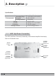
2. Description Specifications Item Specifications Operating Temp Environmental Humidity Cooling method Voltage Current Frequency Leakage Current Û&a Û& Û)a Û) a 5+ Convection $& a 9 6A Max / 6V, 12V, 27VDC a +] W\SLFDO 0.5mA max.@110V AC 2.2.3 UDC (Up Down Converter) The UDC (Up Down Converter) is basically a bi-directional amplifier that sharply filters out unwanted noise.
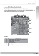
The MCU (Main Control Unit) is the control unit of iDEN MINI. It controls and monitors operational parameters. It is also responsible for generating an alarm, an event log and many other functions of the iDEN MINI. J1 J2 2. Description 2.2.
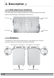
2. Description 2.2.5 HPAs (High Power Amplifiers) The HPAs (High Power Amplifiers) amplifies the transmitted signal from a base station at the final stage of the repeater and vice versa. RF Input RF Output RF Output RF Input 2.2.6 Multiplexer A multiplexer is a device that combines two or more signals onto a common channel or medium to increase its transmission efficiency.
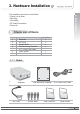
3. Hardware Installation 2. Description The installation procedure is as follows: • Check List of Items • Mounting • Grounding • RF Cable Connection • Power On 3.1 Check List of Items Index Items Quantity 1 2 3 4 5 6 7 Repeater AC Cord Anchor Bolts Wall Mounting Template UTP Cross LAN Cable Quick Guide User’s Manual 1 1 4 1 1 1 1 3.1.
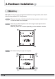
3. Hardware Installation 3.2 Mounting iDEN MINI is easy to mount using the assembled mounting bracket, which has 9 holes for the provided 5/16” fixing screws. 12 Step 1 Remove the cover of double-coated foam tape squares at each corner on the back side of the template. Step 2 Stick the provided template to the wall using the tape squares while adjusting the horizon. Mark the position for 4 screws depending on the installation location. Step 3 Drill holes directly through the template.
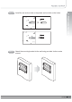
Install the set anchor bolts or the plastic anchor bolts on the holes. Step 5 Attach the mounting bracket to the wall using provided bolts or extra screws. 3.
3. Hardware Installation 14 Step 6 Lean the iDEN MINI to hang the topside of the Guide Ring on the mounting bracket, and push toward the wall to mount. Step 7 Fix the iDEN MINI using 8 screws provided.
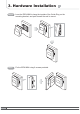
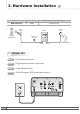
3. Hardware Installation 3.3 Grounding A rod on the left side is intended for a building ground. Connect the ground cable to the rod. Warning Dangerously high voltages may occur and damage the equipment if the equipment is not grounded properly. 3.4 RF Cable Connection Step 1 Connect a cable from a donor antenna to the DONOR ANTENNA Port. Step 2 Connect a cable from a repeater’s service antenna to the SERVER ANTENNA Port. Warning DO NOT connect or disconnect the coaxial cable while the power is on.
3. Hardware Installation Model Max Gain Minimum required isolation RSN-iDEN-25-C 65dB Donor Antenna Repeater Plugged in an AC outlet Base Station Donor Server 3.5 Power On 16 Server Antenna Step 1 Connect the power cord. Step 2 Plug the power cord into a wall outlet. Step 3 Power Switch turns on. Step 4 Check if the green LED at the bottom turns on.
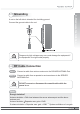
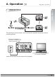
4. Operation 4. Operation 4.1 Connections The remote port allows remote users to access the repeater through an external monitoring device. Power on the switch to “I” The switch is located on the bottom of the main body. Connect UTP Cross LAN Cable to a PC and the iDEN MINI. Local port provides on-site access to the repeater.
4. Operation 4.2 System Requirements iDEN MINI operates on a customer provided PC based platform with the following system requirements : • Windows® 2000, Windows® XP or Windows® Vista • Internet Explorer 6.0(Recommended) or higher • 128 MB RAM or higher • Pentium Ɉ processor or higher • RJ-45 jack required 4.3 Network Setup 4.3.1 Windows XP Step 1 18 Click the Start button and My Network Places.
Click View network connections. Step 3 Right-click Local Area Connection to see a shortcut menu and click Properties. 4.
4. Operation 20 Step 4 Select Internet Protocol (TCP/IP) and click Properties. Step 5 Check Obtain an IP address automatically and click OK. Step 6 Close all windows.
Step 1 Click the Start button, point to Settings, and then click Network and Dial-up Connections. Step 2 Right-click Local Area Connection to see a shortcut menu and click Properties. User’s Manual 4. Operation 4.3.
4. Operation 22 Step 3 Select Internet Protocol (TCP/IP) and click Properties. Step 4 Check Obtain an IP address automatically and click OK. Step 5 Close all windows.
Step 1 Click the Start button and Control Panel. Step 2 Click Network and Internet. 4. Operation 4.3.
4. Operation 24 Step 3 Click Network and Sharing Center. Step 4 Click View status of Local Area Connection.
Click Properties and a caution pop-up window will appear. Click OK. Step 6 Select Internet Protocol Version 4 (TCP/IPv4) and click Properties. 4.
4. Operation Step 7 Check Obtain an IP address automatically and click OK. Step 8 Close all windows. 4.4 System Login Step 1 26 Open your Web browser and type “192.168.0.1:83” into the URL address box. Then press the Enter key.
The logon screen will appear. Type “operator” for the ID and “rtron” for the password and then click OK. Step 3 The pop-up message for the login success will appear. Click OK. User’s Manual 4.