
User`s manual


22 Jackrabbit (BL1800)
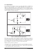
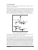
There is a 10 kΩ resistor, R31, connected between Vcc and AD0. This resistor should pro-
vide an appropriate voltage divider bias for a variety of common thermistors so that they
can be connected directly between AD0 and ground. The A/D converter load is the 10 kΩ
resistor connected to Vcc. Remove R31 if a smaller load is desired—this will lead to a
very high input impedance for the A/D converter.
The A/D converter has no reference voltage. There is a relative accuracy between mea-
surements, but no absolute accuracy. This is because Vcc can vary ±5%, the pulse-width
modulated outputs might not reach the full 0 V and 5 V rails out of the Rabbit 2000 micro-
processor, and the gain resistors used in the circuit have a 1% tolerance. For these reasons,
each Jackrabbit needs to be calibrated individually, with the constants held in software, to
be able to rely on an absolute accuracy. The Jackrabbit is sold without this calibration sup-
port.
The algorithm provided to perform the conversion does a successive approximation search
for the analog voltage. This takes an average of 150 ms, and a maximum of 165 ms, with a
14.7 MHz Jackrabbit.