RabbitCore RCM2000 C-Programmable Module User’s Manual 019–0077 • 090417–K
RabbitCore RCM2000 User’s Manual Part Number 019-0077 • 090417–K • Printed in U.S.A. ©2001–2009 Digi International Inc. • All rights reserved. No part of the contents of this manual may be reproduced or transmitted in any form or by any means without the express written permission of Digi International. Permission is granted to make one or more copies as long as the copyright page contained therein is included.
TABLE OF CONTENTS Chapter 1. Introduction 1 1.1 Features .................................................................................................................................................1 1.2 Advantages of Using the RCM2000 .....................................................................................................2 1.3 Development and Evaluation Tools......................................................................................................3 1.3.1 Development Kit .....
.5 Other Hardware .................................................................................................................................. 32 4.5.1 Clock Doubler ............................................................................................................................ 32 4.5.2 Spectrum Spreader...................................................................................................................... 33 4.6 Memory .......................................................
1. INTRODUCTION The RabbitCore RCM2000 series is a family of microprocessor modules designed to be the heart of embedded control systems, providing an array of I/O and addressing. Throughout this manual, the term RCM2000 refers to the complete series of RCM2000 RabbitCore modules unless other production models are referred to specifically. The RCM2000 is a core module designed to be the heart of your own controller built around the plug-in module.
• External reset input • Reset output • Five 8-bit timers, two 10-bit timers; five timers are cascadable in pairs • 256K flash EPROM, 512K SRAM • Real-time clock • Watchdog supervisor • Provision for customer-supplied backup battery via connections on header J2 • Four CMOS-compatible serial ports: maximum asynchronous baud rate of 806,400 bps, maximum synchronous baud rate of 6.45 Mbps. Two ports are configurable as clocked ports.
1.3 Development and Evaluation Tools 1.3.1 Development Kit A complete Development Kit, including a Prototyping Board and Dynamic C development software, is available for the RCM2000. The Development Kit puts together the essentials you need to design an embedded microprocessor-based system rapidly and efficiently. 1.3.2 Development Kit Contents The RCM2000 Development Kit contains the following items: • RCM2020 module with 256K flash memory and 128K SRAM.
1.4 How to Use This Manual This user’s manual is intended to give users detailed information on the RCM2000 module. It does not contain detailed information on the Dynamic C development environment. 1.4.1 Additional Product Information In addition to the product-specific information contained in the RabbitCore RCM2000 User’s Manual (this manual), several higher level reference manuals are provided in HTML and PDF form on the accompanying CD-ROM.
2. HARDWARE SETUP This chapter describes the RCM2000 hardware in more detail, and explains how to set up the accompanying Prototyping Board. NOTE: This chapter (and this manual) assume that you have the RabbitCore RCM2000 Development Kit. If you purchased an RCM2000 module by itself, you will have to adapt the information in this chapter and elsewhere to your test and development setup.
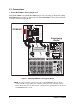
2.1 Connections 1. Attach RCM2000 to Prototyping Board Turn the RCM2000 so that the Rabbit 2000 microprocessor is facing as shown below. Plug RCM2000 headers J1 and J2 on the bottom side of the RCM2000 into the sockets of headers J1 and J3 on the Prototyping Board.
2. Connect RCM2000 to PC Connect the 10-pin connector of the programming cable labeled PROG to header J3 on the RCM2000 module as shown in Figure 2 below. Be sure to orient the red edge of the cable towards pin 1 of the connector. (Do not use the DIAG connector, which is used for a normal serial connection.) AC Adapter The holes shown near J1 and J2 at the top of the RCM2000 exist to align the board for factory testing. Do not use these holes for mounting.
3. Power Supply Connections When all other connections have been made, you can connect power to the Prototyping Board. First, prepare the AC adapter for the country where it will be used by selecting the plug. The RCM2000 Development Kit presently includes Canada/Japan/U.S., Australia/N.Z., U.K., and European style plugs.
2.2 Run a Sample Program Once the RCM2000 is connected as described in the preceding pages, start Dynamic C by double-clicking on the Dynamic C icon on your desktop or in your Start menu. Dynamic C uses the serial port specified during installation. If you are using a USB port to connect your computer to the RCM2000 module, choose Options > Project Options and select “Use USB to Serial Converter” under the Communications tab, then click OK. Find the file PONG.C, which is in the Dynamic C SAMPLES folder.
2.3 Where Do I Go From Here? If everything appears to be working, we recommend the following sequence of action: 1. Run all of the sample programs described in Chapter 3 to get a basic familiarity with Dynamic C and the RCM2000’s capabilities. 2. For further development, refer to the RabbitCore RCM2000 User’s Manual for details of the module’s hardware and software components. A documentation icon should have been installed on your workstation’s desktop; click on it to reach the documentation menu.
3. RUNNING SAMPLE PROGRAMS To develop and debug programs for the RCM2000 (and for all other Rabbit hardware), you must install and use Dynamic C. Dynamic C is an integrated development system for writing embedded software. It runs on an IBM-compatible PC and is designed for use with Rabbit single-board computers and other single-board computers based on the Rabbit microprocessor. Chapter 3 provides the sample programs related to the RCM2000. 3.
3.1.1 Running Sample Program FLASHLED.C This sample program will be used to illustrate some of the functions of Dynamic C. First, open the file FLASHLED.C, which is in the SAMPLES/RCM2000 folder. The program will appear in a window, as shown in Figure 3 below (minus some comments). Use the mouse to place the cursor on the function name WrPortI in the program and type . This will bring up a documentation box for the function WrPortI.
• A message reports “No Rabbit Processor Detected” in cases where the RCM2000 and the Prototyping Board are not connected together, the wall transformer is not connected, or is not plugged in. (The red power LED lights whenever power is connected.) • The programming cable must be connected to the RCM2000. (The colored wire on the programming cable is closest to pin 1 on header J3 on the RCM2000, as shown in Figure 2.) The other end of the programming cable must be connected to the PC serial port.
You can set break points while the program is running by positioning the cursor to a statement and using the F2 key. If the execution thread hits the break point, a break point will take place.You can toggle the break point off with the F2 key and continue execution with the F9 key. Try this a few times to get the feel of things. 3.1.1.4 Editing the Program Click on the Edit box on the task bar. This will set Dynamic C into the edit mode so that you can change the program.
• Setting break points. The F2 key is used to turn on or turn off (toggle) a break point at the cursor position if the program has already been compiled. You can set a break point if the program is paused at a break point. You can also set a break point in a program that is running at full speed. This will cause the program to break if the execution thread hits your break point. • Watch expressions. A watch expression is a C expression that is evaluated on command in the watch window.
#define DS2 0 #define DS3 1 // predefine for LED DS2 // predefine for LED DS3 // This cofunction flashes LED on for ontime, then off cofunc flashled[4](int led, int ontime, int offtime) { for(;;) { waitfor(DelayMs(ontime)); WrPortI(PADR,&PADRShadow,(1<
3.1.1.8 Advantages of Cooperative Multitasking Cooperative multitasking, as implemented with language extensions, has the advantage of being intuitive. Unlike preemptive multitasking, variables can be shared between different tasks without having to take elaborate precautions. Sharing variables between tasks is the greatest cause of bugs in programs that use preemptive multitasking.
3.1.2 Getting to Know the RCM2000 The following sample programs can be found in the SAMPLES\RCM2000 folder. • EXTSRAM.C—demonstrates the setup and simple addressing to an external SRAM. This program first maps the external SRAM to the I/O Bank 0 register with a maximum of 15 wait states, chip select strobe (which is ignored because of the circuitry), and allows writes. The first 256 bytes of SRAM are cleared and read back. Values are then written to the same area and are read back.
• FLASHLEDS.C—demonstrates the use of coding with assembly instructions, cofunctions, and costatements to flash LEDs DS2 and DS3 on the Prototyping Board on and off. LEDs DS2 and DS3 are controlled by Parallel Port A bit 0 (PA0) and Parallel Port A bit 1 (PA1).Once you have compile this program and it is running, LEDs DS2 and DS3 will flash on/off at different rates. • FLASHLEDS2.C—demonstrates the use of cofunctions and costatements to flash LEDs DS2 and DS3 on the Prototyping Board on and off.
• LCD_DEMO.C—demonstrates a simple setup for an LCD that uses the HD44780 controller or an equivalent. Connect the LCD to the RCM2000 address and data lines on the Prototyping Board.
3.1.3 Serial Communication The following sample programs can be found in the SAMPLES\RCM2000 folder. PWR D2 S1 DS1 DS2 PA1 DS3 2 23 X A M S3 PA0 PB2 S2 JP1DS2 U1 C1+ RESET J5 RN1 S2 DS3 PB3 S3 C2 U2 C3 RS-232 C4 C5 J6 RXC TXC Two sample programs, CORE_FLOWCONTROL.C and CORE_PARITY.C, are available to illustrate RS-232 communication.
22 RabbitCore RCM2000
4. HARDWARE REFERENCE Chapter 4 describes the principal subsystems for the RCM2000. 4.1 RCM2000 Digital Inputs and Outputs Figure 4 shows the subsystems designed into the RCM2000. PA0PA7 Port A 4x CMOS synchronous/ asynchronous PCLK RESET WDO Serial Ports (Port C) Programming Port PB0 PB5 PB6 PB7 Port B RCM2000 Misc.
The RCM2000 has 40 parallel I/O lines grouped in five 8-bit ports available on headers J1 and J2. The 24 bidirectional I/O lines are located on pins PA0–PA7, PD0-PD7, and PE0PE7. The pinouts for headers J1 and J2 are shown in Figure 5.
The ports on the Rabbit 2000 microprocessor used in the RCM2000 are configurable, and so the factory defaults can be reconfigured. Table 2 lists the Rabbit 2000 factory defaults and the alternate configurations. Table 2.
Table 2.
As shown in Table 2, pins PA0–PA7 can be used to allow the Rabbit 2000 to be a slave to another processor. PE0, PE1, PE4, and PE5 can be used as external interrupts INT0A, INT1A, INT0B, and INT1B. Pins PB0 and PB1 can be used to access the clock on Serial Port B and Serial Port A of the Rabbit microprocessor. Pins PD4 and PD6 can be programmed to be optional serial outputs for Serial Ports B and A. PD5 and PD7 can be used as alternate serial inputs by Serial Ports B and A. 4.1.
4.2 Memory I/O Interface Thirteen of the Rabbit 2000 address lines (A0–A12) and all the data lines (D0–D7) are available as outputs on the RCM2000. I/0 write (/IOWR), I/0 read (/IORD), buffer enable (/BUFEN), and Watchdog Output (/WDO) are also available for interfacing to external devices. The STATUS output has three different programmable functions: 1. It can be driven low on the first op code fetch cycle. 2. It can be driven low during an interrupt acknowledge cycle. 3.
4.3.2 Programming Port The RCM2000 has a 10-pin program header labeled J3. The programming port uses the Rabbit 2000’s Serial Port A for communication. Dynamic C uses the programming port to download and debug programs. The programming port is also used for the following operations. • Cold-boot the Rabbit 2000 after a reset. • Remotely download and debug a program over an Ethernet connection using the RabbitLink EG2110.
4.4 Serial Programming Cable The programming cable is used to connect the RCM2000’s programming port to a PC serial COM port. The programming cable converts the RS-232 voltage levels used by the PC serial port to the TTL voltage levels used by the Rabbit 2000. When the PROG connector on the programming cable is connected to the RCM2000’s programming header, programs can be downloaded and debugged over the serial interface.
4.4.2 Standalone Operation of the RCM2000 The RCM2000 must be programmed via the RCM2000 Prototyping Board or via a similar arrangement on a customer-supplied board. Once the RCM2000 has been programmed successfully, remove the programming cable from the programming connector and reset the RCM2000. The RCM2000 may be reset by cycling the power off/on or by pressing the RESET button on the Prototyping Board. The RCM2000 module may now be removed from the Prototyping Board for end-use installation.
4.5 Other Hardware 4.5.1 Clock Doubler The RCM2000 takes advantage of the Rabbit 2000 microprocessor’s internal clock doubler. A built-in clock doubler allows half-frequency crystals to be used to reduce radiated emissions. The 25.8 MHz (RCM 2000 and RCM2010) and 18.4 MHz (RCM 2020) frequencies are generated using 12.9 MHz and 9.2 MHz crystals. The clock doubler is disabled automatically in the BIOS for crystals with a frequency above 12.9 MHz. The clock doubler can be disabled if 25.8 MHz or 18.
4.5.2 Spectrum Spreader RCM2000 RabbitCore modules that have a Rabbit 2000 microprocessor labeled IQ4T (or higher) are equipped with a Rabbit 2000 microprocessor that has a spectrum spreader, which helps to mitigate EMI problems. By default, the spectrum spreader is on automatically for RCM2000 modules that carry the IQ4T (or higher) marking when used with Dynamic C 7.30 or later versions, but the spectrum spreader may also be turned off or set to a stronger setting.
4.6 Memory 4.6.1 SRAM The RCM2000 is designed to accept 32K to 512K of SRAM packaged in an SOIC case. 4.6.2 Flash EPROM The RCM2000 is also designed to accept 128K to 512K of flash EPROM packaged in a TSOP case. NOTE: Rabbit recommends that any customer applications should not be constrained by the sector size of the flash EPROM since it may be necessary to change the sector size in the future. Writing to arbitrary flash memory addresses at run time is also discouraged.
5. SOFTWARE REFERENCE Dynamic C is an integrated development system for writing embedded software. It runs on an IBM-compatible PC and is designed for use with Rabbit single-board computers and other single-board computers based on the Rabbit microprocessor. Chapter 4 provides the libraries and function calls related to the RCM2000. 5.1 More About Dynamic C Dynamic C has been in use worldwide since 1989. Dynamic C is specially designed for programming embedded systems.
5.1.1 Using Dynamic C You have a choice of doing your software development in the flash memory or in the SRAM included on the RCM2000. The flash memory and SRAM options are selected with the Options > Project Options > Compiler menu. The advantage of working in RAM is to save wear on the flash memory, which is limited to about 100,000 write cycles. The disadvantage is that the code and data might not both fit in RAM.
• Standard debugging features: X Breakpoints—Set breakpoints that can disable interrupts. X Single-stepping—Step into or over functions at a source or machine code level, µC/OS-II aware. X Code disassembly—The disassembly window displays addresses, opcodes, mnemonics, and machine cycle times. Switch between debugging at machine-code level and source-code level by simply opening or closing the disassembly window.
5.2 I/O The RCM2000 was designed to interface with other systems, and so there are no drivers written specifically for this purpose. The general Dynamic C read and write functions allow you to customize the parallel I/O to meet your specific needs. For example, use WrPortI(PEDDR, &PEDDRShadow, 0x00); to set all the port E bits as inputs, or use WrPortI(PEDDR, &PEDDRShadow, 0xFF); to set all the port E bits as outputs. The sample programs in the Dynamic C SAMPLES directory provide further examples. 5.2.
5.3 Serial Communication Drivers Library files included with Dynamic C provide a full range of serial communications support. The RS232.LIB library provides a set of circular-buffer-based serial functions. The PACKET.LIB library provides packet-based serial functions where packets can be delimited by the 9th bit, by transmission gaps, or with user-defined special characters.
5.4 Upgrading Dynamic C Dynamic C patches that focus on bug fixes are available from time to time. Check the Web site www.rabbit.com/support/ for the latest patches, workarounds, and bug fixes. The default installation of a patch or bug fix is to install the file in a directory (folder) different from that of the original Dynamic C installation. Rabbit recommends using a different directory so that you can verify the operation of the patch without overwriting the existing Dynamic C installation.
APPENDIX A. SPECIFICATIONS Appendix A provides the specifications for the RCM2000, and describes the conformal coating.
A.1 Electrical and Mechanical Specifications Figure A-1 shows the mechanical dimensions for the RCM2000. 2.300 1.300 Please refer to the RCM2000 footprint diagram later in this appendix for precise header locations. (58.4) 2.200 (55.9) (33.0) 0.100 (2.5) TP1 R4 R6 U5 TP4 /RSTI /RESO GND VCC J3 (9.5) C8 C9 R7D2 D3 (48.3) SRAM 1.900 U2 A12 A10 A8 A6 A4 A2 A0 PC0 PC2 PC4 PC6 PD0 PD2 PD4 PD6 GND VBAT SM0 (45.
It is recommended that you allow for an “exclusion zone” of 0.04" (1 mm) around the RCM2000 in all directions when the RCM2000 is incorporated into an assembly that includes other printed circuit boards. An “exclusion zone” of 0.08" (2 mm) is recommended below the RCM2000 when the RCM2000 is plugged into another assembly using the shortest connectors for header J1. Figure A-2 shows this “exclusion zone.” 0.28 2.380 (2) 0.08 (7.2) (60.4) 2.300 1.980 (50.3) (2) 0.08 (7.2) 0.28 (58.
Table A-1 lists the electrical, mechanical, and environmental specifications for the RCM2000. Table A-1. RCM2000 Specifications Parameter Microprocessor RCM2000 Rabbit 2000® at 25.8 MHz Flash EPROM SRAM Backup Battery General-Purpose I/O Additional Inputs Additional Outputs Memory, I/O Interface Serial Ports Serial Rate Slave Interface Real-Time Clock Timers Watchdog/Supervisor Power RCM2010 Rabbit 2000® at 18.
A.1.1 Headers The RCM2000 uses headers at J1, J2, and J3 for physical connection to other boards. J1 and J2 are 2 × 20 SMT headers with a 2 mm pin spacing. J3 is a 2 × 5 header with a 2 mm pin spacing. Figure A-3 shows the layout of another board for the RCM2000 to be plugged in to. These reference design values are relative to the mounting hole or to the header connectors. 1.960 J1 (49.78) 1.079 J2 (27.41) 0.020 sq typ (0.5) 0.079 (2.0) 1.300 (33.02) 0.079 (2.0) 0.125 dia (3.2) Figure A-3.
A.2 Bus Loading You must pay careful attention to bus loading when designing an interface to the RCM2000. This section provides bus loading for external devices. Table A-2 lists the capacitance for the various RCM2000 I/O ports. Table A-2. Capacitance of RCM2000 I/O Ports I/O Ports Input Capacitance (pF) Output Capacitance (pF) Typ. Max. Typ. Max.
The values from the table above are derived using 55 ns (25.8 MHz version) and 90 ns (18.4 MHz version) memory access times. External capacitive loading can be improved by 10 pF for commercial temperature ranges, but do not exceed 100 pF. See the AC timing specifications in the Rabbit 2000 Microprocessor User’s Manual for more information. Figure A-4 shows a typical timing diagram for the Rabbit 2000 microprocessor memory read and write cycles.
A.3 Rabbit 2000 DC Characteristics Table A-4 outlines the DC characteristics for the Rabbit 2000 at 5.0 V over the recommended operating temperature range from Ta = –40°C to +85°C, VDD = 4.5 V to 5.5 V. Table A-4. 5.0 Volt DC Characteristics Symbol 48 Parameter Test Conditions Min IIH Input Leakage High VIN = VDD, VDD = 5.5 V IIL Input Leakage Low (no pull-up) VIN = VSS, VDD = 5.5 V -10 IOZ Output Leakage (no pull-up) VIN = VDD or VSS, VDD = 5.
A.4 I/O Buffer Sourcing and Sinking Limit Unless otherwise specified, the Rabbit I/O buffers are capable of sourcing and sinking 8 mA of current per pin at full AC switching speed. Full AC switching assumes a 25.8 MHz CPU clock and capacitive loading on address and data lines of less than 100 pF per pin. Address pin A0 and data pin D0 are rated at 16 mA each. Pins A1–A12 and D1–D7 are each rated at 8 mA. The absolute maximum operating voltage on all I/O is VDD + 0.5 V, or 5.5 V.
A.5 Conformal Coating The area around the crystal oscillator has had the Dow Corning silicone-based 1-2620 conformal coating applied. The conformally coated area is shown in Figure A-5. The conformal coating protects these high-impedance circuits from the effects of moisture and contaminants over time.
A.6 Jumper Configurations Figure A-6 shows the header locations used to configure the various RCM2000 options via jumpers. JP3 JP1 JP2 Top Side Bottom Side 175-0201 Figure A-6. Location of RCM2000 Configurable Positions Table A-6 lists the configuration options. Table A-6.
52 RabbitCore RCM2000
APPENDIX B. PROTOTYPING BOARD Appendix B describes the features and accessories of the Prototyping Board, and explains the use of the Prototyping Board to demonstrate the RCM2000 and to build prototypes of your own circuits.
B.1 Overview of the Prototyping Board The Prototyping Board included in the Development Kit makes it easy to connect an RCM2000 module to a power supply and a PC workstation for development. It also provides an array of basic I/O peripherals (switches and LEDs), as well as a prototyping area for more advanced hardware development. For the most basic level of evaluation and development, the Prototyping Board can be used without modification.
User’s Manual /BEN /IOW PE1 PE3 PE5 PE7 D1 D3 D5 D7 PCLK PB6 PB4 PB2 PB0 PA6 PA4 PA2 GND PC7 PD1 PD3 PD5 PD0 PD2 PD4 C3 C4 C5 /RSTI GND VCC S3 JP1DS2 S2 PWR S3 RESET S1 J6 (102) RS-232 RXC TXC RN1 4.
Table B-1 lists the electrical, mechanical, and environmental specifications for the Prototyping Board. Table B-1. Prototyping Board Specifications Parameter 56 Specification Board Size 4.00" × 4.30" × 1.19" (102 mm × 110 mm × 30 mm) Operating Temperature –40°C to +70°C Humidity 5% to 95%, noncondensing Input Voltage 7.5 V to 25 V DC Maximum Current Draw (including user-added circuits) 1 A at 12 V and 25°C, 0.7 A at 12 V and 70ºC Prototyping Area 2" × 3" (51 mm × 76 mm) throughhole, 0.
B.3 Power Supply The RCM2000 requires a regulated 5 V ± 0.25 V DC power source to operate. Depending on the amount of current required by the application, different regulators can be used to supply this voltage. The Prototyping Board has an onboard LM340-T5 or equivalent. The LM340-T5 is an inexpensive linear regulator that is easy to use. Its major drawback is its inefficiency, which is directly proportional to the voltage drop across it. The voltage drop creates heat and wastes power.
B.4 Using the Prototyping Board The Prototyping Board is actually both a demonstration board and a prototyping board. As a demonstration board, it can be used to demonstrate the functionality of the RCM2000 right out of the box without any modifications to either board. There are no jumpers or dip switches to configure or misconfigure on the Prototyping Board so that the initial setup is very straightforward.
Table B-2. Prototyping Board Jumper Settings Header JP2 Pins Description 1–2 PA0 to LED DS2 3–4 PA1 to LED DS3 5–6 PB2 to Switch S2 7–8 PB3 to Switch S3 Note that the pinout at location JP1 on the bottom side of the Prototyping Board (shown in Figure B-4) is a mirror image of the top side pinout. The Prototyping Board provides the user with RCM2000 connection points brought out conveniently to labeled points at headers J2 and J4 on the Prototyping Board.
A pair of small holes capable of holding 30 AWG wire appears to the side of each hole pair at locations J2 and J4 for convenience of point-to-point wiring when headers are installed. The signals are those of the adjacent pairs of holes at J2 and J4. These small holes are also provided for the components that may be installed below location J4. There is an additional 2" × 3" of through-hole prototyping space available on the Prototyping Board.
B.4.1 Adding Other Components There is room on the Prototyping Board for a user-supplied RS-232 transceiver chip at location U2 and a 10-pin header for serial interfacing to external devices at location J6. A Maxim MAX232 transceiver is recommended. When adding the MAX232 transceiver at position U2, you must also add 100 nF charge storage capacitors at positions C3–C6 as shown in Figure B-7.
62 RabbitCore RCM2000
APPENDIX C. POWER MANAGEMENT Appendix C describes the RCM2000 power circuitry. C.1 Power Supplies The RCM2000 requires a regulated 5 V ± 0.25 V DC power source. An RCM2000 with no loading at the outputs operating at 18.432 MHz typically draws 88 mA, and an RCM2000 operating at 25.8048 MHz typically draws 120 mA. The RCM2000 will consume 13 mA to 15 mA of additional current when the programming cable is used to connect J3 to a PC. C.1.
The drain on the battery by the RCM2000 is typically 10 µA when no other power is supplied. If a 950 mA·h battery is used, the battery can last more than 6 years: 950 mA·h ------------------------ = 10.8 years (shelf life = 10 years). 10 µA Since the shelf life of the battery is 10 years, the battery can last for its full shelf life. The actual life in your application will depend on the current drawn by components not on the RCM2000 and the storage capacity of the battery. C.1.
C.1.3 Power to VRAM Switch The VRAM switch, shown in Figure C-3, allows a customer-supplied external battery to provide power when the external power goes off. The switch provides an isolation between Vcc and the battery when Vcc goes low. This prevents the Vcc line from draining the battery. VRAM VCC Q11 FDV302P R16 10 kW /RES_OUT R15 22 kW Q10 MMBT3904 Figure C-3.
C.2 Chip Select Circuit Figure C-4 shows a schematic of the chip select circuit. VRAM R28 /CSRAM Q14 /CS1 Q13 R15 /RES C6 1 nF 22 kW Q10 R5 100 kW Figure C-4. Chip Select Circuit The current drain on the battery in a battery-backed circuit must be kept to a minimum. When the RCM2000 is not powered, the battery keeps the SRAM memory contents and the real-time clock (RTC) going. The SRAM has a powerdown mode that greatly reduces power consumption.
APPENDIX D. SAMPLE CIRCUITS Appendix D provides these sample circuits that incorporate the RCM2000.
D.1 RS-232/RS-485 Serial Communication RS-232 1 RCM2000 Core Module V+ V C1+ 100 nF J2 100 nF 3 C1 4 C2+ 5 C2 VCC 100 nF 2 6 100 nF 19 PC4 11 T1IN T1OUT 14 TXB 17 PC2 10 T2IN T2OUT 7 TXC 20 PC5 12 R1OUT R1IN 13 RXB 18 PC3 9 R2OUT R2IN 8 RXC 15 PC0 4 D 16 PC1 1 R RCM2000 Core Module J2 RS-485 VCC 680 W A 28 PD5 47 kW 3 2 B DE 6 7 485+ 220 W 485 680 W RE SP483EN Figure D-1. Sample RS-232 and RS-485 Circuits Sample Program: PUTS.
D.2 Keypad and LCD Connections RCM2000 Core Module VCC J1 10 kW resistors PB0 PB2 PB3 PB4 PB5 11 13 14 15 16 J2 Keypad Row 0 Row 2 Row 3 Row 4 Row 5 PC1 PD6 PD7 20 29 30 Row 1 Col 0 Col 1 NC NC Figure D-2. Sample Keypad Connections Sample Program: KEYLCD.C in SAMPLES\COREMODULE. Rabbit 2000 Core Module 4 5 6 7 8 9 10 PA1 PA2 PA3 PA4 PA5 PA6 PA7 100 nF 680 W 3 470 W 1 kW 2.2 kW 4.
D.3 LCD Connections 2x20 LCD DB0DB7 D0D7 RCM2000 Core Module 2x20 LCD D0D7 DB0DB7 /PE0 /IOR /IOW /PE1 E E Figure D-4. Sample LCD Connections Sample Program: LCD_DEMO.C in SAMPLES\COREMODULE. The shaded part of the circuit in Figure D-4 can be used to drive a second LCD, but additional software not included in LCD_DEMO.C will have to be written.
D.4 External Memory The sample circuit can be used with an external 64 Kbit memory device. Larger SRAMs can be written to using this scheme by using other available Rabbit 2000 ports (parallel ports A to E) as address lines. 8K × 8 SRAM Rabbit 2000 Core Module A0A12 A0A12 D0D7 D0D7 /WE /OE /CE /IOW /IOR /BEN Figure D-5. Sample External Memory Connections Sample Program: EXTSRAM.C in SAMPLES\COREMODULE.
D.5 Simple D/A Converter The output will initially be 0 V to -10.05 V after the first inverting op-amp, and 0 V to +10.05 V after the second inverting op-amp. All lows produce 0 V out, FF produces 10 V out. The output can be scaled by changing the feedback resistors on the op-amps. For example, changing 5.11 kΩ to 2.5 kΩ will produce an output from 0 V to -5 V (first stage) and 0 V to 5 V (second stage). Op-amps with a very low input offset voltage are recommended.
INDEX A telephone-based technical support .......................... 40 upgrades and patches ........ 40 USB port settings ................ 9 hardware connections ............. 6 install RCM2000 on Prototyping Board ........................ 6 power supply ....................... 8 programming cable ............. 7 hardware reset ......................... 8 pinout Prototyping Board ..............59 RCM2000 ..........................24 alternate configurations ...............................
sample programs ................... 11 FLASHLED.C ................... 12 getting to know the RCM2000 EXTSRAM.C ................ 18 FLASHLED.C ............... 18 FLASHLED2.C ............. 18 FLASHLEDS.C ............. 19 FLASHLEDS2.C ........... 19 KEYLCD.C ................... 19 LCD_DEMO.C .............. 20 SWTEST.C .................... 20 TOGGLELED.C ............ 20 PONG.C .............................. 9 serial communication CORE_FLOWCONTROL.C ..................................... 21 CORE_PARITY.C ........
SCHEMATICS 090-0097 RCM2000 Schematic www.rabbit.com/documentation/schemat/090-0097.pdf 090-0099 RCM2000 Prototyping Board Schematic www.rabbit.com/documentation/schemat/090-0099.pdf 090-0128 Programming Cable Schematic www.rabbit.com/documentation/schemat/090-0128.pdf You may use the URL information provided above to access the latest schematics directly.