Wildcat (BL2000) C-Programmable Single-Board Computer with Ethernet User’s Manual 019–0094 • 090529–O
Wildcat (BL2000) User’s Manual Part Number 019-0094 • 090529–O • Printed in U.S.A. ©2001–2009 Digi International Inc. • All rights reserved. No part of the contents of this manual may be reproduced or transmitted in any form or by any means without the express written permission of Digi International. Permission is granted to make one or more copies as long as the copyright page contained therein is included.
TABLE OF CONTENTS Chapter 1. Introduction 1 1.1 BL2000 Description..............................................................................................................................1 1.2 BL2000 Features...................................................................................................................................1 1.2.1 Connector Options ........................................................................................................................2 1.
.2 Sample Programs................................................................................................................................ 38 4.2.1 General BL2000 Sample Programs ............................................................................................ 38 4.2.2 Digital I/O................................................................................................................................... 38 4.2.3 Serial Communication .................................................
1. INTRODUCTION The BL2000 is a high-performance, C-programmable singleboard computer that offers built-in digital and analog I/O combined with Ethernet connectivity in a compact form factor. A Rabbit® 2000 microprocessor operating at 22.1 MHz provides fast data processing. An optional plastic enclosure is available, and may be wall-mounted or panel-mounted. 1.
• Backup battery. • Ability to send e-mail and serve Web pages containing embedded data from singleboard computer. • Remote program downloading and debugging capability via RabbitLink. • Boards with the CE mark are CE-compliant. • Optional plastic enclosure (can be wall-mounted or panel-mounted) and LED light pipes (enclosure and light pipes are included with the Tool Kit, and are also sold separately). Appendix A provides detailed specifications. Four models of the BL2000 are available.
1.3 Development and Evaluation Tools 1.3.1 Tool Kit A Tool Kit contains the hardware essentials you will need to use your own BL2000 singleboard computer. The items in the Tool Kit and their use are as follows: • Getting Started instructions. • Dynamic C CD-ROM, with complete product documentation on disk. • Programming cable, used to connect your PC serial port to the BL2000. • Universal AC adapter, 12 V DC, 1 A (includes Canada/Japan/U.S., Australia/N.Z., U.K., and European style plugs).
1.3.2 Software The BL2000 is programmed using version 7.04 or later of Rabbit’s Dynamic C. A compatible version is included on the Tool Kit CD-ROM. Dynamic C v. 9.60 includes the popular µC/OS-II real-time operating system, point-to-point protocol (PPP), FAT file system, RabbitWeb, and other select libraries that were previously sold as individual Dynamic C modules.
1.4 CE Compliance Equipment is generally divided into two classes. CLASS A CLASS B Digital equipment meant for light industrial use Digital equipment meant for home use Less restrictive emissions requirement: less than 40 dB µV/m at 10 m (40 dB relative to 1 µV/m) or 300 µV/m More restrictive emissions requirement: 30 dB µV/m at 10 m or 100 µV/m These limits apply over the range of 30–230 MHz. The limits are 7 dB higher for frequencies above 230 MHz.
1.4.1 Design Guidelines Note the following requirements for incorporating the BL2000 series of single-board computers into your application to comply with CE requirements. General • The power supply provided with the Tool Kit is for development purposes only. It is the customer’s responsibility to provide a CE-compliant power supply for the end-product application.
2. GETTING STARTED Chapter 2 explains how to connect the programming cable and power supply to the BL2000. 2.1 BL2000 Connections 1. Attach the BL2000 to the plastic enclosure base. Position the BL2000 over the plastic enclosure base as shown below in Figure 2. Attach the BL2000 to the base at the top left and bottom right positions using the two 4-40 × ¼ screws supplied with the enclosure.
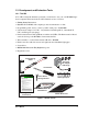
2. Connect the programming cable to download programs from your PC and to debug the BL2000. Connect the 10-pin PROG connector of the programming cable to header J5 on the BL2000. Ensure that the colored edge lines up with pin 1 as shown. (Do not use the DIAG connector, which is used for a normal serial connection.) Connect the other end of the programming cable to a COM port on your PC.
3. Connect the power supply. First, prepare the AC adapter for the country where it will be used by selecting the plug. The BL2000 Tool Kit presently includes Canada/Japan/U.S., Australia/N.Z., U.K., and European style plugs. Snap in the top of the plug assembly into the slot at the top of the AC adapter as shown in Figure 4, then press down on the spring-loaded clip below the plug assembly to allow the plug assembly to click into place.
2.2 Installing Dynamic C If you have not yet installed Dynamic C version 7.04 (or a later version), do so now by inserting the Dynamic C CD in your PC’s CD-ROM drive. The CD will auto-install unless you have disabled auto-install on your PC. If the CD does not auto-install, click Start > Run from the Windows Start button and browse for the Dynamic C setup.exe file on your CD drive. Click OK to begin the installation once you have selected the setup.exe file.
2.3 Starting Dynamic C Once the BL2000 is connected to your PC and to a power source, start Dynamic C by double-clicking on the Dynamic C icon on your desktop or in your Start menu. Dynamic C defaults to using the serial port on your PC that you specified during installation. If the port setting is correct, Dynamic C should detect the BL2000 and go through a sequence of steps to cold-boot the BL2000 and to compile the BIOS.
2.4 PONG.C You are now ready to test your set-up by running a sample program. Find the file PONG.C, which is in the Dynamic C SAMPLES folder. To run the program, open it with the File menu (if it is not still open), compile it using the Compile menu, and then run it by selecting Run in the Run menu. The STDIO window will open and will display a small square bouncing around in a box.
3. SUBSYSTEMS Chapter 3 describes the principal subsystems for the BL2000. • Digital I/O • Relay Outputs • Serial Communication • A/D Converter Inputs • D/A Converter Outputs • Memory • External Interrupts Figure 5 shows these Rabbit-based subsystems designed into the BL2000. BL2000 Programming Port 32 kHz 11 MHz osc osc RS-232 Digital Inputs Digital Outputs RS-485 SRAM Flash RABBIT 2000 Relay Output A/D Converter Ethernet D/A Converter Figure 5.
3.1 BL2000 Pinouts The BL2000 pinouts are shown in Figure 6(a) and Figure 6(b).
3.1.1 Headers and Screw Terminals All BL2000 models are equipped with 1 × 12 screw terminal strips (J2, J4, J8, and J9) and a 2-pin power jack (J7). The BL2000 and BL2010 also have the RJ-45 Ethernet jack (J6). There is provision on the circuit board to accommodate one of the following types of connectors instead of the screw-terminal strips. • 2 × 17 IDC headers with a pitch of 0.1". • 1 × 17 friction-lock connectors with a pitch of 0.1". • 1 × 17 bottom-mount sockets with a pitch of 0.1".
3.1.2 Power Supply Pins Instead of connecting an AC adapter to the power supply jack, J7, the input power supply (9 V to 40 V DC) may be connected to pins 12 and 11 on header J2 (see Figure 6(a) or Figure 6(b)). Pin 12 on header J9 or J10 is normally GND by factory default, but may be changed to Vcc by removing resistor R161 and installing resistor R160. See Appendix C, “Power Supply,” for more information on this configuration and for information on backupbattery options.
3.2 Digital I/O 3.2.1 Digital Inputs The BL2000 has 11 digital inputs, IN0–IN10, each of which is protected over a range of –36 V to +36 V. The inputs are factory-configured to be pulled up to +5 V, but they can also be pulled down by moving the surface-mounted jumper at JP6 as shown in Figure 7. JP6 JP6 3 Vcc 1 Factory Default 27 kW 22 kW 10 nF Rabbit 2000 Microprocessor GND Figure 7(a).
JP6 3 Vcc 1 27 kW 22 kW 10 nF Rabbit 2000 Microprocessor Figure 7(c). Example of Logic Gate Driving BL2000 Digital Input The actual switching threshold is approximately 2.40 V for channels IN0–IN10. Anything below this value is a logic 0, and anything above is a logic 1. The A/D converter inputs can be used as additional digital inputs using the parameters specified for the digIn software function call. The default threshold for channels IN11– IN21 is also set to 2.
3.2.2 Digital Outputs The BL2000 has 10 digital outputs, OUT0–OUT9, each of which can either sink or source up to 200 mA, depending on how the outputs are configured. On boards that carry the CE mark, OUT8 and OUT9 are each capable of sinking up to 750 mA. Each output can be configured individually as either a sinking or a sourcing output as shown in Figure 9. The outputs can be pulled as a group to Vcc, +K, or GND through 27 kΩ resistors.
Figure 9. BL2000 Digital Outputs The locations of the output pull-up/pull-down select resistors R32, R34, and R35 are shown in Figure 10.
3.3 Relay Outputs Figure 11 shows the BL2000 relay contact connections. A diode across the coil provides a return path for inductive spikes, and snubbers across the relay contacts protect the relay contacts from inductive spikes. 9 11 J9 Vcc 1 10 Rabbit 2000 Microprocessor 10 8 COM 7 NO 9 NC 3 COM 4 NO 2 NC 47 W 100 nF 47 W 100 nF Figure 11. BL2000 Relay Output Contact Connections The relay is driven by PA0, which is the same Rabbit 2000 parallel port that drives OUT0 and LED DS4.
3.4 Serial Communication The BL2000 has one RS-232 serial channel (with RTS/CTS) or two RS-232 (3-wire) channels, one RS-485 serial channel, and one CMOS serial channel. The RS-232 channel(s) are configured with the serMode software function call. Table 2 summarizes the options. Table 2. Serial Communication Configurations Serial Port Mode B C D 0 RS-232, 3-wire RS-232, 3-wire RS-485 1 RS-232, 5-wire CTS/RTS RS-485 All four serial ports operate in an asynchronous mode.
RST- IN1 IN0 485- GND J4 J3 AGND C75 R5 C79 AGND R2 AG ND C78 R3 AGND C5 C7 AGND R8 U3 R18 R21 J12 C9 C12 R14 AGND DAC1 DAC0 ADC8 ADC7 ADC6 ADC5 ADC4 ADC3 ADC2 ADC1 ADC0 C2C3 AGND C8 U2 C4 R7 C76 R152 C11 R11 R10 R157 JP1 R17 C13 J1 J2 +RAW GND GND R1 +K GND RST- IN1 GND R4 R6 IN0 GND GND C18 485+ RXD2 TXD2 RXD1 TXD1 J5 R13C1 R9 Y3 C19 Y2 U5 J4 J3 GN AGND C75 R5 C79 AGND C4 R7 C76 R152 C11 R11 R10 R157 JP1 R17 C13 R2 AGND R23 C14 R3 AG ND C78 AGN
The BL2000 comes with a 220 Ω termination resistor and two 681 Ω bias resistors installed and enabled with jumpers across pins 1–2 and 3–4 on header JP1, as shown in Figure 13.
The transformer/connector assembly ground is connected to the BL2000 printed circuit board digital ground via a 0 Ω resistor “jumper,” R1, as shown in Figure 15. RJ-45 Ethernet Plug R1 Board Ground Chassis Ground Figure 15. Isolation Resistor R1 The factory default is for the 0 Ω resistor “jumper” at R1 to be installed. In high-noise environments, it may be useful to ground the transformer/connector assembly directly through the chassis ground.
Alternate Uses of the Serial Programming Port All three clocked Serial Port A signals are available as • a synchronous serial port • an asynchronous serial port, with the clock line usable as a general CMOS input The serial programming port may also be used as a serial port via the DIAG connector on the serial programming cable. In addition to Serial Port A, the Rabbit 2000 startup-mode (SMODE0, SMODE1), status, and reset pins are available on the serial programming port.
3.5 A/D Converter Inputs The single 14-channel A/D converter used in the BL2000 has a resolution of 12 bits (models BL2000 and BL2020) or 10 bits (models BL2010 and BL2030). Eleven of the 14 channels are available externally, and three are used internally for the reference voltages: 4.096 V (Vref), 2.048 V (Vref/2), and Analog Ground. These internal voltages can be used to check the functioning of the A/D converter. The A/D converter only measures voltages between 0 V and the applied reference voltage.
3.6 D/A Converter Outputs Figure 18 shows the analog voltage reference circuit. +V 100 W DAC_PWR 14 kW 100 nF 4.096 V ref diode 4.096_VREF JP3 3 2 1 +V 453 W 1.707_VREF 10 kW 100 nF Figure 18. Analog Reference Voltages This circuit generates the 4.096 V reference voltage, which is used by the A/D converter and optionally by the two D/A converters. This sets the operating range of the A/D converter and the D/A converters (0–4.096 V).
Only the BL2000 and the BL2020 models are stuffed with D/A converters. The D/A converters provide only a voltage output. This means that in order to maintain the maximum accuracy of the D/A converters, only a small amount of current should be drawn from the D/A converter output (of the order of µA). With D/A converters installed, the user has the option of using an unbuffered A/D converter input to read the output of a D/A converter or one of the two fixed voltages +V or Vcc.
3.7 Memory Section A.3, “Jumper Configurations,” shows where the 0 Ω surface-mounted “jumpers” described in this section are found. 3.7.1 SRAM The BL2000 is designed to accept 128K to 512K of SRAM packaged in an SOIC case. The standard models come with 128K of SRAM. Table 3 lists the jumper settings for the jumpers used to set the SRAM size. The “jumpers” are 0 Ω surface-mounted resistors. Table 3. Memory Jumper Selections SRAM (JP5) Flash Memory (JP4) 1–2 128K 1–2 128K/256K 2–3 512K 2–3 512K 3.7.
3.8 Programming Cable The programming cable is used to connect the BL2000’s programming port to a PC serial COM port. The programming cable converts the RS-232 voltage levels used by the PC serial port to the TTL voltage levels used by the Rabbit 2000. When the PROG connector on the programming cable is connected to the BL2000’s programming header, programs can be downloaded and debugged over the serial interface.
3.9 Other Hardware 3.9.1 External Interrupts BL2000 boards with a Rabbit 2000 microprocessor labeled IQ3T or higher have external interrupts available on digital inputs IN2 and IN3. Older BL2000 boards (Rabbit 2000 microprocessors labeled IQ2T) have one external interrupt available—see Technical Note TN301, Rabbit 2000 Microprocessor Interrupt Problem, for further information on how to use this interrupt on the older boards. 3.9.
3.9.3 Spectrum Spreader BL2000 boards that carry the CE mark have a Rabbit 2000 microprocessor that features a spectrum spreader, which helps to mitigate EMI problems. By default, the spectrum spreader is on automatically for BL2000 boards that carry the CE mark when used with Dynamic C 7.32 or later versions, but the spectrum spreader may also be turned off or set to a stronger setting. The means for doing so is through a simple configuration macro as shown below. 1.
34 Wildcat (BL2000)
4. SOFTWARE Dynamic C is an integrated development system for writing embedded software. It runs on an IBM-compatible PC and is designed for use with Rabbit-based single-board computers and other devices based on the Rabbit microprocessor. Chapter 4 provides the libraries, function calls, and sample programs related to the BL2000. 4.1 An Overview of Dynamic C Dynamic C has been in use worldwide since 1989.
Dynamic C has a number of standard features: • Full-feature source and/or assembly-level debugger, no in-circuit emulator required. • Royalty-free TCP/IP stack with source code and most common protocols. • Hundreds of functions in source-code libraries and sample programs: X Exceptionally fast support for floating-point arithmetic and transcendental functions. X RS-232 and RS-485 serial communication. X Analog and digital I/O drivers. X I2C, SPI, GPS, file system. X LCD display and keypad drivers.
4.1.1 Upgrading Dynamic C 4.1.1.1 Patches and Bug Fixes Dynamic C patches that focus on bug fixes are available from time to time. Check the Web site www.rabbit.com/support/ for the latest patches, workarounds, and bug fixes. The default installation of a patch or bug fix is to install the file in a directory (folder) different from that of the original Dynamic C installation.
4.2 Sample Programs Sample programs are provided in the Dynamic C SAMPLES folder. The sample program PONG.C demonstrates the output to the STDIO window. The various directories in the SAMPLES folder contain specific sample programs that illustrate the use of the corresponding Dynamic C libraries. The SAMPLES\BL2000 folder provides sample programs specific to the BL2000. Each sample program has comments that describe the purpose and function of the program.
• PWM.C—Demonstrates the use of Timer B to generate a PWM signal on digital output OUT8. The program generates a 42 Hz PWM signal with the duty cycle adjustable from 1 to 99%. • RELAY.C—Demonstrates how to control the relay on the BL2000. 4.2.3 Serial Communication The following sample programs are found in the RS232 subdirectory in SAMPLES/BL2000. • PUTS.C—Transmits and then receives an ASCII string on Serial Ports B and C. It also displays the serial data received from both ports in the STDIO window.
4.2.5 D/A Converter Outputs The following sample programs are found in the DAC subdirectory in SAMPLES/BL2000. • DACAL.C—This program demonstrates how to recalibrate an D/A converter channel using two known voltages, and defines the two coefficients, gain and offset, that will be rewritten into the D/A converter's EEPROM simulated in flash memory. Note that this sample program will overwrite the calibration constants set at the factory. • DAOUT1.
4.3 BL2000 Libraries Two library directories are used to develop applications for the BL2000. • BL2000-—libraries associated with features specific to the BL2000. • TCPIP—libraries specific to using TCP/IP functions on the BL2000. Other generic functions applicable to all devices based on the Rabbit 2000 microprocessor are described in the Dynamic C Function Reference Manual.
4.4 BL2000 Function Calls 4.4.1 Board Initialization void brdInit (void); Call this function at the beginning of your program. This function initializes the system I/O ports and loads all the A/D and DAC calibration constants from flash memory into SRAM for use by your program.
Function Output Function State Port I/O PC2 Output RTS/TXC RS-232 Inactive high PC3 Input CTS/RXC RS-232 N/A PC4 Output TXB RS-232 Inactive high PC5 Input RXB RS-232 N/A PC6 Output TXA Programming Port Inactive high PC7 Input RXA Programming Port N/A PD0 Output DAC-ADC_SK On PD1 Output DAC-ADC_SDI On PD2 Input RTL-ADC_SDO N/A PD3 Input RTL_SK N/A* PD4 Output RTL_SDI On PD5 Output DAC0_CS Inactive high PD6 Output DAC1_CS Inactive high PD7 Output ADC_C
4.4.2 Digital I/O int digIn(int channel); Reads the state of an input channel: IN0–IN10—standard digital inputs, ± 36 V DC IN11–IN14—pseudo digital inputs using A/D converter inputs ADC0–ADC3, ± 10 V DC IN15–IN19—pseudo digital inputs using A/D converter inputs ADC4–ADC8, 0 V to 48 V DC IN20–IN21—pseudo digital inputs using A/D converter inputs DAC0–DAC1, 0 V to 48 V DC (BL2010 and BL2030) The threshold is fixed at 2.40 V for channels IN0–IN10. Anything below 2.
4.4.3 Serial Communication Library files included with Dynamic C provide a full range of serial communications support. The RS232.LIB library provides a set of circular-buffer-based serial functions. The PACKET.LIB library provides packet-based serial functions where packets can be delimited by the 9th bit, by transmission gaps, or with user-defined special characters.
4.4.4 Relay and LED Outputs void relayOut(int relay, int value); Sets the state of a relay. The relay is driven by PA0, which is the same Rabbit 2000 parallel port that drives OUT0 and LED DS4. OUT0 therefore works in parallel with the relay output. Rabbit therefore recommends that you do not use OUT0 for a digital output when you are using the relay. PARAMETERS relay is the relay to control, 0 = Relay 0.
4.4.5 A/D Converter Inputs void anaInCalib(int channel, int value1, float volts1, int value2, float volts2); Calibrates the response of the A/D converter channel as a linear function using the two conversion points provided. Gain and offset constants are calculated and placed into global table _adcInCalib. PARAMETERS channel is the A/D converter input channel (0–10). value1 is the first A/D converter channel value. volts1 is the voltage corresponding to the first A/D converter channel value.
TLC1543 commands (the TLC1543 is a 10-bit A/D converter) D7–D4 Channel 0 - 10 Channel 11 = (Vref+ - Vref-)/2 Channel 12 = VrefChannel 13 = Vref+ (No software power-down mode available) D3–D0 No specific values assigned. PARAMETERS cmd is the A/D converter input channel (0–10) to read.
float anaInVolts(unsigned int channel); Reads the state of an A/D converter input channel and uses the previously set calibration constants to convert it to volts. PARAMETER channel is the A/D converter input channel (0–10). RETURN VALUE A voltage value corresponding to the voltage on the analog input channel.
4.4.6 D/A Converter Outputs The functions in this section apply only to the BL2000 and the BL2020 models. int anaOutCalib(int channel, int value1, float volts1, int value2, float volts2); Calibrates the response of the D/A converter channel desired as a linear function using the two conversion points provided. Gain and offset constants are calculated and placed into global table _dacCalib. PARAMETERS channel is the D/A converter output channel (0 or 1). value1 is the first D/A converter value.
void anaOut(unsigned int channel, unsigned int modecount); Sets the voltage of a D/A converter output channel by serially clocking in 16 bits to a D/A converter using the following format: D15–D14 Doesn’t matter. D13–D12 Mode of operation 00—Normal Operation 01—Software Powerdown, 1 kΩ to GND 10—Software Powerdown, 100 kΩ to GND 11—Software Powerdown, three-state D11–D0 Data bits, MSB–LSB (0–4095) PARAMETERS channel is the D/A converter output channel to write (0 or 1).
void anaOutVolts(unsigned int channel, float voltage); Sets the voltage of a D/A converter output channel by using the previously set calibration constants to calculate the correct data values. PARAMETERS channel is the D/A converter output channel (0 or 1). voltage is the voltage desired on the output channel.
5. USING THE TCP/IP FEATURES Chapter 5 provides an introduction to using the TCP/IP features on your BL2000 board. 5.1 TCP/IP Connections Before proceeding you will need to have the following items. • If you don’t have Ethernet access, you will need at least a 10Base-T Ethernet card (available from your favorite computer supplier) installed in a PC. • Two RJ-45 straight through Ethernet cables and a hub, or an RJ-45 crossover Ethernet cable.
The PC running Dynamic C through the serial programming port on the BL2000 does not need to be the PC with the Ethernet card. 3. Apply Power Plug in the AC adapter. The BL2000 is now ready to be used. NOTE: A hardware RESET is accomplished by unplugging the AC adapter, then plugging it back in, or by momentarily grounding the board reset input at pin 9 on screw terminal header J2.
5.2 TCP/IP Sample Programs We have provided a number of sample programs demonstrating various uses of TCP/IP for networking embedded systems. These programs require that you connect your PC and the BL2000 together on the same network. This network can be a local private network (preferred for initial experimentation and debugging), or a connection via the Internet. 5.2.1 How to Set IP Addresses in the Sample Programs With the introduction of Dynamic C 7.
5.2.2 How to Set Up your Computer’s IP Address for a Direct Connection When your computer is connected directly to the BL2000 via an Ethernet connection, you need to assign an IP address to your computer. To assign the PC the address 10.10.6.101 with the netmask 255.255.255.0, do the following. Click on Start > Settings > Control Panel to bring up the Control Panel, and then double-click the Network icon.
5.3 Run the PINGME.C Sample Program Connect the crossover cable from your computer’s Ethernet port to the BL2000’s RJ-45 Ethernet connector. Open this sample program from the SAMPLES\TCPIP\ICMP folder, compile the program, and start it running under Dynamic C. When the program starts running, the green LNK light on the BL2000 should be on to indicate an Ethernet connection is made.
5.4 Running More Sample Programs With a Direct Connection The program SSI.C (SAMPLES\BL2000\TCPIP\) demonstrates how to make the BL2000 a Web server. This program allows you to turn the LEDs on an attached Demonstration Board from the Tool Kit on and off from a remote Web browser. LEDs DS4–DS8 on the BL2000 will match those on the Web page.
APPENDIX A. SPECIFICATIONS Appendix A provides the specifications for the BL2000 and describes the conformal coating.
A.1 Electrical and Mechanical Specifications Figure A-1 shows the mechanical dimensions for the BL2000. 0.120 dia × 4 (3.0) + G PWR LNK C46 C47 C48 GND C49 GND C50 C51 GN D C52 GND GND GND J11 J9 IN3 IN4 IN5 IN6 IN7 IN8 IN9 IN10 OUT8 OUT9 GND OUT0 OUT1 OUT2 OUT3 OUT4 OUT5 OUT6 OUT7 NO COM NC (54) (87) 2.11 0.65 C45 (16.5) GND DS8 C37 C42 C44 Q6 J8 J10 IN2 3.
Table A-1 lists the electrical, mechanical, and environmental specifications for the BL2000. Table A-1. BL2000 Specifications Feature BL2000 BL2020 10Base-T, LNK and ACT LEDs None Flash Memory 256K (standard) SRAM 128K (standard) Backup Battery Digital Inputs BL2030 Rabbit 2000® at 22.
Table A-1. BL2000 Specifications (continued) Feature Timers Watchdog/Supervisor Power Operating Temperature BL2000 BL2010 BL2020 BL2030 Five 8-bit timers (four are cascadable from the first) and one 10-bit timer with two match registers Yes 9–40 V DC or 24 V AC (±10%), 1.5 W max. –40°C to +70°C Humidity 5–95%, noncondensing Board Size 3.43" × 4.15" × 0.
A.1.1 Headers The BL2000 has an option for 0.1" IDC headers or friction-lock connectors at J1, J3, J10, and J11 for physical connection to other boards or ribbon cables. Figure A-2 shows the BL2000 footprint. These values are relative to one of the mounting holes. 3.380 (85.9) 3.189 (81.0) 1.239 (31.5) 0.760 (19.3) (67.1) 2.641 (66.0) (57.9) (53.7) 2.598 J12 2.113 J6 J3 J5 2.280 J1 J7 (9.2) (12.4) 0.361 0.487 J11 J10 1.589 (40.4) 2.839 (72.1) Figure A-2.
A.2 Conformal Coating The areas around the crystal oscillator and the battery backup circuit on the BL2000 have had the Dow Corning silicone-based 1-2620 conformal coating applied. The conformally coated areas are shown in Figure A-3. The conformal coating protects these high-impedance circuits from the effects of moisture and contaminants over time.
A.3 Jumper Configurations Figure A-4 shows the header locations used to configure the various BL2000 options via jumpers. JP1 JP2 Top Side GND JP3 JP4 JP5 JP6 TP15 R160 GND R161 TP17 R118 Bottom Side Figure A-4.
Table A-2 lists the configuration options. Table A-2.
A.4 Use of Rabbit 2000 Parallel Ports Figure A-5 shows the Rabbit-based subsystems designed into the BL2000. PB0 PB5 PA0PA7 Port A (OUT0OUT7) PC0PC5 Port B (IN6IN10, CTRL) Programming Port DA0DA7 Data Lines RAM Port D (ADC, DAC, Eth) RABBIT Serial Ports (Port C) PC6PC7 PD2 PD3 PB6 PB7 PE2PE7 Port E (IN0IN5 OUT8OUT9) 2000 Real-Time Clock Watchdog 7 Timers Slave Port Clock Doubler PD0 PD1 PD4 PB7 PE0, PE1 Address Lines A0A18 IORD IOWR I/O Control Misc.
Table A-3.
APPENDIX B. PLASTIC ENCLOSURE The plastic enclosure provides a secure way to protect your BL2000. The enclosure itself may be mounted on any flat surface. Appendix B describes how to mount the BL2000 inside the plastic enclosure, how to install the optional light pipes, and provides details on mounting the assembly.
B.1 Assembly 1. Attach the BL2000 to the plastic enclosure base. Position the BL2000 over the plastic enclosure base as shown below in Figure B-1. Attach the BL2000 to the base using the two 4-40 × ¼ screws supplied.
3. Attach the enclosure top to the base. Position the enclosure top over the plastic enclosure base as shown below in Figure B-3. Attach the enclosure top to the base using the two 4-40 × ½ screws supplied. If you installed the light pipes, be sure they are aligned over the LEDs as shown.
B.2 Dimensions 4. (1 25 08 ) Figure B-4 shows the dimensions for the plastic enclosure. 0.70 (18) 0.375" (9.5 mm) is cut off each corner 5.00 (127) 4.35 (1 75 24 ) 4.8 1.3 (3 75 5) 2.1 (5 3 4) 3.6 (9 2 2) (110) 0.25 (6.4) 2.85 (72) 1.375 (35) 5.60 (142) Figure B-4. Plastic Enclosure Dimensions When fully assembled with the BL2000 installed, the total height of the plastic enclosure will be 1.1" (28 mm).
APPENDIX C. POWER SUPPLY Appendix C describes the power circuitry distributed on the BL2000. C.1 Power Supplies Power is supplied to the BL2000 via a mini phone jack located at J7 or through the screw terminal strip, header J2. The BL2000 itself is protected against reverse polarity by a diode at D1 as shown in Figure C-1. SWITCHING POWER REGULATOR +RAW POWER IN J2 orJ7 D1 DCIN TVS1 C28 47 µF 14 15 8 1 12 U12 7 17 18 LM2575 Vcc 10 2 1 4 330 µH D2 L1 1N5819 3 C29 330 µF Figure C-1.
C.1.1 Power for Analog Circuits Power to the analog circuits is provided by way of a two-stage low-pass filter, which isolates the analog section from digital noise generated by the other components. The analog power voltage +V powers the op-amp for the buffered A/D converter inputs, the A/D converter, and the 4.096 V reference circuit. The two D/A converters can be powered either from the reference, which is the standard, or from +V when ratiometric measurements are desired.
C.2.1 Replacing the Backup Battery The battery is user-replaceable, and is fitted in a battery holder. To replace the battery, lift up on the spring clip and slide out the old battery. Use only a Panasonic CR2330 or equivalent replacement battery, and insert it into the battery holder with the + side facing up. NOTE: The SRAM contents and the real-time clock settings will be lost if the battery is replaced with no power applied to the BL2000.
C.2.3 Power to VRAM Switch The VRAM switch, shown in Figure C-3, allows the battery backup to provide power when the external power goes off. The switch provides an isolation between Vcc and the battery when Vcc goes low. This prevents the Vcc line from draining the battery. VCC R99 VRAM 0W Q9 FDV302P R93 11 kW /RESET R104 22 kW Q8 MMBT3904 Figure C-3.
C.2.4 Reset Generator The BL2000 uses a reset generator, U4, to reset the Rabbit 2000 microprocessor when the voltage drops below the voltage necessary for reliable operation. The reset occurs between 4.50 V and 4.75 V, typically 4.63 V. The reset can be initiated either externally or by a watchdog timeout (WDTOUT) on the Rabbit 2000 microprocessor. +5 V /RESET U4 WDTOUT RESET GENERATOR R151 100 kW R69 22 kW C24 100 nF D15 EXT RESET D17 Figure C-4.
C.3 Chip Select Circuit Figure C-5 shows a schematic of the chip select circuit. VRAM R101 100 kW /CSRAM Q3 /CS1 Q4 R104 /RESET 22 kW Q8 C81 1 nF Figure C-5. Chip Select Circuit The current drain on the battery in a battery-backed circuit must be kept at a minimum. When the BL2000 is not powered, the battery keeps the SRAM memory contents and the real-time clock (RTC) going. The SRAM has a powerdown mode that greatly reduces power consumption.
Transistors Q3 and Q4 are of opposite polarity so that a rail-to-rail voltage can be passed. When the /CS1 voltage is low, Q4 will conduct. When the /CS1 voltage is high, Q3 conducts. It takes time for the transistors to turn on, creating a propagation delay. This propagation delay is typically very small, about 10 ns to 15 ns. The signal that turns the transistors on is a high on the processor’s reset line, /RESET.
80 Wildcat (BL2000)
APPENDIX D. DEMONSTRATION BOARD Appendix D shows how to connect the Demonstration Board to the BL2000. D.1 Connecting Demonstration Board Before running sample programs based on the Demonstration Board, you will have to connect the Demonstration Board from the BL2000 Tool Kit to the BL2000 board. Proceed as follows. 1. Use the wires included in the BL2000 Tool Kit to connect header J1 on the Demonstration Board to header J8 and J9 on the BL2000.
AGND BT1 DS5 + G GND C45 C46 C47 C48 GND C49 GND C50 C51 GN D C52 DS8 C37 C42 C44 Q6 GND GND GND J8 J10 J11 J9 IN2 IN3 IN4 IN5 IN6 IN7 IN8 IN9 IN10 OUT8 OUT9 GND OUT0 OUT1 OUT2 OUT3 OUT4 OUT5 OUT6 OUT7 J1 · · · · · · · · · · · · LED1 LED2 LED3 LED4 BUZZER LED4 LED3 LED2 LED1 K +5V 1-2 3-4 5-6 DEMO BOARD BUZZER H1 ·· ·· ·· ·· ·· ·· ·· SW4 H2 SW3 SW2 SW1 GND Jumpers: H1: None H2: As shown BL2000 BAD DS7 + Q5 DS6 + DS4 + 10 GND DS3 K1 Q4 D
User’s Manual 83 5-6 3-4 8-7 BUZZER · · · · · · · · · · · · J1 BUZZER LED4 LED3 LED2 LED1 K +5V SW2 SW4 LED1 LED2 LED3 LED4 SW1 GND DEMO BOARD 1-2 H2 SW3 ·· ·· ·· ·· ·· ·· ·· H1 SW4 6-5 SW3 4-3 SW2 2-1 Figure D-2.
84 Wildcat (BL2000)
INDEX A D A/D converter function calls _anaIn ............................ 47 anaIn .............................. 48 anaInCalib ..................... 47 anaInEERd .................... 49 anaInEEWr .................... 49 anaInVolts ..................... 49 analog I/O reference voltages ............. 28 analog inputs ......................... 27 use as digital inputs ........... 27 analog outputs ....................... 28 D/A converter function calls anaOut ........................... 51 anaOutCalib ...
IP addresses ...........................56 how to set ..........................55 how to set PC IP address ...56 J jumper configurations .....65, 66 Demonstration Board ..82, 83 J9(12) .................................73 J9(12) is GND ...................66 J9(12) is Vcc ......................66 JP1 (RS-485 bias and termination resistors) ...........24, 66 JP2 (flash memory bank select) ......................30, 66 JP3 (D/A converter power supply) .....................
specifications dimensions BL2000 ......................... 60 plastic enclosure ............ 72 electrical ............................ 61 header footprint ................. 63 headers .............................. 63 relative pin 1 locations ...... 63 temperature ....................... 61 spectrum spreader ................. 33 subsystems ...................... 13, 14 T U USB/serial port converter ....... 8 Dynamic C settings ........... 11 V Vcc J9(12) ................................
88 Wildcat (BL2000)
SCHEMATICS 090-0117 BL2000 Schematic www.rabbit.com/documentation/schemat/090-0117.pdf 090-0042 Demonstration Board Schematic www.rabbit.com/documentation/schemat/090-0042.pdf 090-0128 Programming Cable Schematic www.rabbit.com/documentation/schemat/090-0128.pdf You may use the URL information provided above to access the latest schematics directly.