Racal Instruments™ 3152B VXIbus Arbitrary Waveform Generator User Manual Also including the 3151B, 3100M, and 3100R Publication No. 980935 Rev. M Astronics Test Systems Inc. 4 Goodyear, Irvine, CA 92618 Tel: (800) 722-2528, (949) 859-8999; Fax: (949) 859-7139 atsinfo@astronics.com atssales@astronics.com atshelpdesk@astronics.com http://www.astronicstestsystems.com Copyright 2009 by Astronics Test Systems Inc. Printed in the United States of America. All rights reserved.
THANK YOU FOR PURCHASING THIS ASTRONICS TEST SYSTEMS PRODUCT For this product, or any other Astronics Test Systems product that incorporates software drivers, you may access our web site to verify and/or download the latest driver versions. The web address for driver downloads is: http://www.astronicstestsystems.com/support/downloads If you have any questions about software driver downloads or our privacy policy, please contact us at: atsinfo@astronics.
RETURN OF PRODUCT Authorization is required from Astronics Test Systems before you send us your product or sub-assembly for service or calibration. Call or contact Customer Support at 1-800-722-3262 or 1-949-859-8999 or via fax at 1949-859-7139. We can also be reached at: atshelpdesk@astronics.com. If the original packing material is unavailable, ship the product or sub-assembly in an ESD shielding bag and use appropriate packing materials to surround and protect the product.
FOR YOUR SAFETY Before undertaking any troubleshooting, maintenance or exploratory procedure, read carefully the WARNINGS and CAUTION notices. This equipment contains voltage hazardous to human life and safety, and is capable of inflicting personal injury. If this instrument is to be powered from the AC line (mains) through an autotransformer, ensure the common connector is connected to the neutral (earth pole) of the power supply.
This page was intentionally left blank.
Publication No. 980935 Rev. M 3152B User Manual Table of Contents Chapter 1.......................................................................................................................... 1-1 Introduction ..................................................................................................................... 1-1 What’s in This Manual ............................................................................................................... 1-1 What’s in This Chapter ............
3152B User Manual Publication No. 980935 Rev. M Amplitude Hopping ........................................................................................................... 1-18 FSK .................................................................................................................................. 1-18 PSK.................................................................................................................................. 1-18 ASK.................................................
Publication No. 980935 Rev. M 3152B User Manual Power On/Reset Defaults .......................................................................................................... 3-3 Turning the Output On ............................................................................................................... 3-3 Turning the SYNC Output On .................................................................................................... 3-3 Selecting the SYNC Source ...............................
3152B User Manual Publication No. 980935 Rev. M Counter/Timer Limitations ................................................................................................ 3-36 Synchronizing through the Local Bus ...................................................................................... 3-37 Using the 3201A/3202A Signal Amplifier ............................................................................. 3-38 Connecting the 3202A/3202A Signal Amplifier ........................................
Publication No. 980935 Rev. M 3152B User Manual Wave Menu ...................................................................................................................... 4-43 The Toolbar ......................................................................................................................... 4-45 The Waveform Screen ......................................................................................................... 4-45 Generating Waveforms Using Equation Editor ...............
3152B User Manual Publication No. 980935 Rev. M Command Separator ............................................................................................................. 5-2 The MIN and MAX Parameters .............................................................................................. 5-2 Querying Parameter Setting .................................................................................................. 5-3 Query Response Format ....................................................
Publication No. 980935 Rev. M 3152B User Manual The SCPI Status Registers ................................................................................................ 5-117 The Status Byte Register (STB) ......................................................................................... 5-117 Reading the Status Byte Register .................................................................................. 5-118 Clearing the Status Byte Register ..................................................
3152B User Manual Publication No. 980935 Rev. M Delayed Trigger Characteristics ....................................................................................... 6-16 Re-trigger Characteristics ................................................................................................ 6-16 Trigger Slope ................................................................................................................... 6-17 Trigger Level ...........................................................
Publication No. 980935 Rev. M 3152B User Manual Calibration and Firmware Update .................................................................................. 7-1 What’s in this Chapter ............................................................................................................... 7-1 Calibration ................................................................................................................................. 7-1 Calibration Types ........................................
3152B User Manual Publication No. 980935 Rev. M Trigger Characteristics .............................................................................................................. A-2 Sources .............................................................................................................................. A-2 Frequency/Time Accuracy ......................................................................................................... A-3 PLL Characteristics ..............................
Publication No. 980935 Rev. M 3152B User Manual Appendix B ...................................................................................................................... B-1 3100M/3100R/3151B/3152B Module Specifications ...................................................... B-1 Input Characteristics ..................................................................................................................B-1 Output Characteristics ............................................................
3152B User Manual Publication No. 980935 Rev. M This page was intentionally left blank.
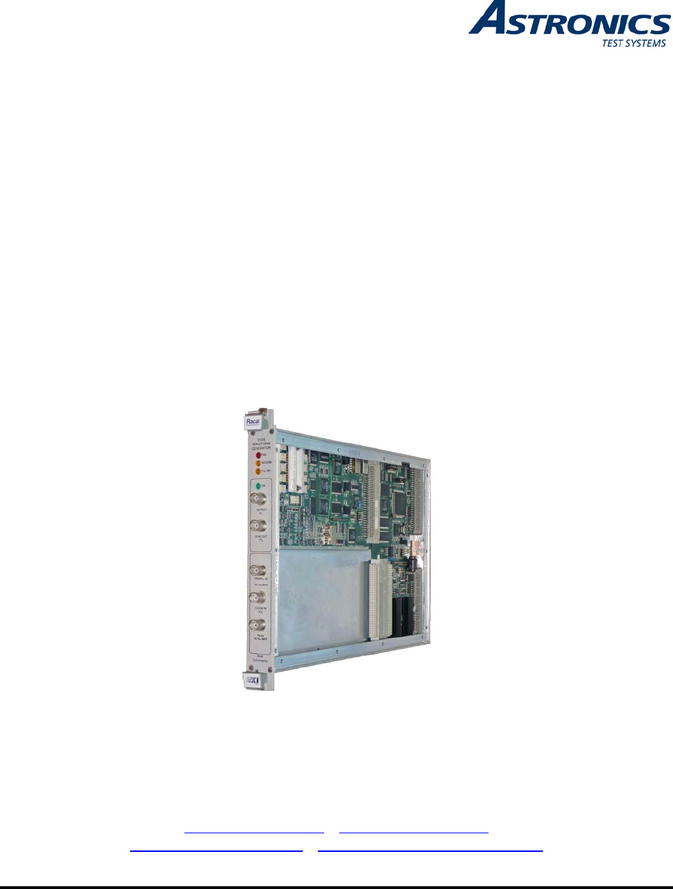
Publication No. 980935 Rev. M 3152B User Manual List of Figures Figure 1-1, Racal Instruments 3152B............................................................................................ 1-3 Figure 1-2, ArbConnection Control Panels .................................................................................... 1-5 Figure 1-3, ArbConnection Wave Composer Example .................................................................. 1-5 Figure 1-4, ArbConnection Pulse Composer Example ................
3152B User Manual Publication No. 980935 Rev. M Figure 4-35, Waveform Screen................................................................................................... 4-46 Figure 4-36, Equation Editor Dialog Box ..................................................................................... 4-47 Figure 4-37, Equation Editor Example ........................................................................................ 4-51 Figure 4-38, Using the Equation Editor to Modulate Sine Waveforms.
Publication No. 980935 Rev. M 3152B User Manual Figure 7-13, Confirmation for Locking Calibration Factors .......................................................... 7-41 Figure 7-14, Firmware Revision Screen ...................................................................................... 7-45 Figure 7-15, Updater Window ..................................................................................................... 7-47 Figure 7-16, Updater Window with Update Button ............................
3152B User Manual Publication No. 980935 Rev. M This page was intentionally left blank.
Publication No. 980935 Rev. M 3152B User Manual List of Tables Table 2-1, Valid and Invalid IP Addresses for Subnet Mask 255.255.255.0 .................................. 2-7 Table 5-1, 3152B SCPI Command Summary for 3152A Emulation............................................... 5-8 Table 5-2, 3152B SCPI Command Summary.............................................................................. 5-14 Table 5-3, Instrument & Output Control Commands Summary ..................................................
3152B User Manual Publication No. 980935 Rev. M Table 6-32, PLL Tests – Frequency ............................................................................................ 6-26 Table 6-33, PLL Tests – Phase Offset ........................................................................................ 6-27 Table 6-34, PLL Tests – PM Phase Offset.................................................................................. 6-28 Table 6-35, Frequency Measurement Accuracy..............................
Publication No. 980935 Rev. M 3152B User Manual DOCUMENT CHANGE HISTORY Revision Date A 1/22/09 B 2/16/12 C 6/20/12 D 6/20/12 E 3/29/13 F 7/9/2013 G 9/24/2013 H 10/29/2013 J 1/9/2014 Astronics Test Systems Description of Change Document Control Release ECN00034 replacing Chapter 6, Performance Checks with updated version. ECN00423 updating 1 Meg calibration information (Chapter 7) and additional configuration information, ECN00600 added Appendix C, 3152A/3152B Comparison.
3152B User Manual Revision xx Publication No. 980935 Rev. M Date K 5/9/14 L 8/15/2014 M 11/7/2014 Description of Change ECN04919 revised calibration procedure in Chapter 7, PLL Adjustments for cleaner signals and improved accuracy. Revised Chapter 6, PLL Checks – Phase Offset for correct length of arbitrary waveform. Added A1 and A2 amplifier documentation, including description, commands, performance checks, and calibration procedure.
Publication No. 980935 Rev. M 3152B User Manual Chapter 1 Introduction What’s in This Manual This manual contains information for operating and servicing the Racal Instruments™ 3151B, 3152B, 3100M-3152B, and 3100R3152B VXIbus Arbitrary Waveform Generators. Generally, what is applicable to the 3152B is the same for the other three models, except where otherwise stated. Throughout this manual, we will refer to all four units as the 3152B.
3152B User Manual Publication No. 980935 Rev. M compatibilities between the 3152A and the 3152B What’s in This Chapter Conventions Used in this Manual This chapter contains a general and functional description of the Racal Instruments 3152B VXIbus Arbitrary Waveform Generator. It also explains the front panel connectors, operational modes, and all available features. However, some options available for the 3152B may not be installed in your specific module.
Publication No. 980935 Rev.
3152B User Manual Publication No. 980935 Rev.
Publication No. 980935 Rev.
3152B User Manual Publication No. 980935 Rev. M Figure 1-4, ArbConnection Pulse Composer Example Figure 1-5, ArbConnection Serial Data Composer Example General Description Output Waveforms This section describes the 3152B general features and performance, as well as output functions, run modes, and functions. The 3152B is a digital waveform generator that creates virtually any type of waveform.
Publication No. 980935 Rev. M 3152B User Manual you may maximize the effective memory capacity by downloading specific waveforms only when they are required. For example, if one part of your ATE sequence requires a complex waveform that consumes nearly all of the waveform memory, you may delete this waveform after that portion of your sequence is completed, and then quickly download a new waveform for the next part of the sequence.
3152B User Manual Publication No. 980935 Rev. M when the application requires synchronization to external events. In Interrupted Run mode, the output is either triggered or gated by external signals. The 3152B accepts a trigger event from the front panel connector, a backplane trigger line, or a software command from your computer. The Run mode and triggering are discussed later in this chapter.
Publication No. 980935 Rev. M 3152B User Manual negative direction. Remote Control Carrier Configuration (Different Model Numbers) As with any other VXIbus instrument, the 3152B must be used with a host computer. All of its functions, modes, and parameters are fully programmable using one of the following three ways: • Low-level programming. Use SCPI commands to program each individual parameter. • ArbConnection.
3152B User Manual Publication No. 980935 Rev. M VXI controller but take control via the LAN port to completely bypass the backplane interface and control instrument functions and parameters from a web page using LXI capabilities. The USB port is used for memory stick I/O where waveform data can be loaded directly to arbitrary waveform memory. This feature was specifically designed for security reasons where breach of secret waveform data can endanger national security if it falls to the wrong hands.
Publication No. 980935 Rev. M 3152B User Manual Figure 1-6, Configurations: 3151B, 3152B, 3100R-3152B, and 3100M-3152B Safety Considerations Astronics Test Systems The 3152B has been manufactured according to international CE safety standards – EN-61010. Adjustments, maintenance, or repair of the unit while the covers are removed and power is applied must be carried out only by skilled, authorized personnel. Removal of the covers without authorization shall immediately void the warranty agreement.
3152B User Manual Options Publication No. 980935 Rev. M The 3100M-3152B and 3100R-3152B are available in two memory configurations. Compare the option number printed on the instrument to verify which option was installed at the factory. Contact your nearest Astronics Test Systems representative if the number printed on the case does not reflect the version ordered. The list of options is given below: -001 - 3152B - basic instrument, with 1MB RAM.
Publication No. 980935 Rev. M 3152B User Manual • EXT 10MHz: A TTL level external 10 MHz reference OR a phase control input for use in PLL mode (software selectable) The 3100M-3152B has the same pattern as described above for the 3100R-3152B but has the following additional functions: OUTPUT (OUT) • LAN (RJ-45): LAN connection for software control • USB 2.
3152B User Manual Publication No. 980935 Rev. M and phase when the TRG/PLL IN level is at logic 0, and a shifted frequency, amplitude, or phase when the TRG/PLL IN level is at logic 1. EXT SCLK (EXT 10MHz) EXT 10MHz The EXT SCLK connector accepts sample clock signals from an external source. It is AC-coupled to accommodate positive ECL (PECL) or negative ECL (NECL) amplitude level clock signals having frequencies from DC to 300 MHz.
Publication No. 980935 Rev. M 3152B User Manual determine the necessary delay time. Nine standard waveform shapes are available: • Sine • Triangle • Square • Pulse/Ramp • Sine(x)/x • Pulse • Gaussian Pulse • Rising/decaying Exponential Pulse • Noise • DC Each waveform has parameters for modifying it to suit your requirements. Arbitrary (User) Waveforms The waveform memory can store one or more arbitrary, or userdefined, waveforms.
3152B User Manual Publication No. 980935 Rev. M Figure 1-7, Segment 1 – Sine (x)/x Waveform Figure 1-8, Segment 2 – Sine Waveform Figure 1-9, Segment 3 – Pulse Waveform The following sequence was made of segment 2 repeated twice, segment 1 repeated four times, and segment 3 repeated two times.
Publication No. 980935 Rev. M 3152B User Manual Figure 1-10, Sequenced Waveforms Modulated Waveforms Sweep The use of direct digital synthesis (DDS) technology makes the 3152B is agile. During operations such as sweep, FSK, FM, and other modulation modes, the 3152B quickly synthesizes the modulated waveform using the DDS circuit. The variety of modulated waveforms are described below. The 3152B can sweep the output frequency between minimum and maximum values that you specify.
3152B User Manual Publication No. 980935 Rev. M AM The AM function modulates the amplitude of the 3152B output waveform. Four standard modulating waveforms are available: sine, triangle, square, and ramp. AM can be used in Continuous, Triggered, and Gated modes. Modulation depth is programmable from 0% to 100% and up to 200% in some cases. Frequency Hopping The Frequency Hopping function causes the output frequency to hop through a sequence of frequencies.
Publication No. 980935 Rev. M 3D Digital Pulse Waveforms 3152B User Manual The 3D function allows you to sweep the output in three dimensions at the same time: frequency, amplitude, and phase. You may operate the 3D function only from the ArbConnection utility. The waveform memory of the 3152B can be programmed as if it were a pulse generator. All pulse parameters are adjustable, including period, pulse width, delay, rise time, and fall time, as well as double pulse parameters.
3152B User Manual Continuous Mode Triggered Mode Publication No. 980935 Rev. M In Continuous mode, the 3152B generates the selected waveform continuously at the selected frequency, amplitude, and offset. The generator will begin waveform generation as soon as the waveform and its parameters have been programmed, and will stop only when turned off or placed in one of the interrupted run modes.
Publication No. 980935 Rev. M 3152B User Manual generators. One repeats itself at pre-programmed intervals from 100 µs to 20 seconds. The other has a programmable delay time. The re-trigger delay is measured from the end of the signal to the start of the next signal and programmed from 100 ns to 20 seconds with a resolution of 20 ns. Modulation Run Modes As previously mentioned, the 3152B has four run modes: Continuous, Triggered, Gated, and Burst.
3152B User Manual PLL Synchronization Publication No. 980935 Rev. M PLL synchronization is another technique for synchronizing multiple waveform generators. In this case, synchronization is not between pairs of 3152B modules, but between the 3152B and any external device that generates signals stable enough to satisfy the PLL input requirements. When placed in this mode, the 3152B measures the profile of the input signal and determine whether or not it is valid.
Publication No. 980935 Rev. M 3152B User Manual protects equipment that remains connected to the output when the mains power fails or the system is powered down. Mechanical relays have a settling time of about 2 ms. Therefore, when writing software, allow enough time for the relay to close before using the signal at the output connector. Programming the 3152B The 3152B has no front panel control; therefore, you must use a computer to communicate with the instrument.
3152B User Manual Publication No. 980935 Rev. M This page intentionally left blank.
Publication No. 980935 Rev. M 3152B User Manual Chapter 2 Installation Preparation for Use Preparation for use includes selecting the required logical address, configuring the Local Bus (if required), and installing the module in a VXIbus chassis. Logical Address Selection The VXIbus Chassis Resource Manager identifies a module in the system by the module’s address. VXIbus logical addresses can range from 0 to 255. However, logical address 0 is reserved for the Resource Manager.
3152B User Manual Local Bus Configuration Publication No. 980935 Rev. M A 3152B can synchronize (phase lock) with other 3152B modules installed in the same VXI chassis. One of the synchronization methods uses the VXI Local Bus lines (LBUS0-LBUS7). The Local Bus has advantages of high bandwidth and the capability to synchronize any quantity of modules in the same chassis.
Publication No. 980935 Rev. M 3152B User Manual in Chapter 5 in the Instrument & Output Control Commands section (see INSTrument:COUPle commands).
3152B User Manual Installation Publication No. 980935 Rev. M If the 3152B is not configured to use the Local Bus, you may install it into any empty slot in the VXIbus chassis except slot 0. If the 3152B is configured for Local Bus operation, then take care to comply with the configuration rules from the previous section. When inserting the instrument into the mainframe, gently rock it back and forth to seat the connectors into the backplane receptacle.
Publication No. 980935 Rev. M 3152B User Manual ArbConnection. Connecting to a LAN Network The 3100M-3152B has a front panel connector that allows connection to a local area network system. This LAN port has three purposes: • Download waveform data directly from an external computer without using the VXIbus controller. • Control the 3152B in a system that does not have a VXIbus slot 0 controller.
3152B User Manual Publication No. 980935 Rev. M There are three LAN parameters that can be modified and adjusted specifically to match your network setting; These are described below. Consult your network administrator for the setting that will best suit your application. Choosing a Static IP Address • IP address - The unique, computer-readable address of a device on your network. An IP address typically is represented as four decimal numbers separated by periods (for example, 192.160.0.233).
Publication No. 980935 Rev. M 3152B User Manual Table 2-1, Valid and Invalid IP Addresses for Subnet Mask 255.255.255.0 IP Address Comment 123.234.45.211 Valid. 123.234.45.213 Valid. The first three numbers match the previous IP address. The fourth number must be a unique number in the range of 1 to 254. 123.202.45.214 Invalid. Second number does not match the previous IP addresses. The first three numbers must match on all IP addresses with subnet mask 255.255.255.0. 123.234.45.0 Invalid.
3152B User Manual Publication No. 980935 Rev. M This page was intentionally left blank.
Publication No. 980935 Rev. M 3152B User Manual Chapter 3 Operation Overview This chapter explains how to operate the 3152B. Unlike a bench-top instrument, the 3152B requires a computer to turn on functions, change parameters, and configure various operating modes. Two software applications are available to control the instrument: VXIplug&play soft front panels (SFPs) and ArbConnection. For the experienced programmer, VXIplug&play drivers and a set of SCPI commands are available.
3152B User Manual Publication No. 980935 Rev. M configuration. Example 2, Model 3100M/R-3152B, default instrument format is Modern • • Output Termination form:inst leg modifies the commands set from Modern to Legacy, *rst is automatically forced and the 3152B parameters are modified to accept the defaults of the Legacy mode. *rst restores factory defaults for Legacy operation. Output signals should be properly terminated to minimize signal reflections or power loss due to an impedance mismatch.
Publication No. 980935 Rev. M 3152B User Manual be double the programmed value, just as it was when running the software with the 3152A, but the accuracy will be improved. Input/Output Protection The 3152B provides protection for its internal circuitry at the input and output connectors. Appendix A specifies the level of protection for each input or output connector. Power On/Reset Defaults At power-up or as a result of a software reset, the 3152B changes all settings to their default values.
3152B User Manual Publication No. 980935 Rev. M therefore, the output impedance remains low regardless of whether the output is on or off. Use the following command to turn the SYNC output on and off: outp 1 outp 0 Turns the SYNC output on Turns the SYNC output off When you apply power or reset the 3152B, the SYNC output defaults to a single pulse that has a fixed width of four sample clock periods.
Publication No. 980935 Rev. M 3152B User Manual outp:sync:sour puls outp:sync:sour zero Changing the SYNC Position and Width Generates a pulse each time a segment waveform is generated. The pulse width is specified in points using the OUTP:SYNC:WIDTh command. This command is a useful alternative to the BIT sync source, especially when the bit pulse is too narrow. It is also helpful when using the 3152B to emulate the sync pulse of another instrument that it is replacing in a test system.
3152B User Manual Publication No. 980935 Rev. M outp 1 volt volt:offs Enable output relay to turn output on Set up the amplitude level Set up the offset level Set up your oscilloscope to observe that the 3152B generates a sine waveform with the following properties: • Frequency: 1 MHz • Offset: 0 V • Amplitude: 5 V The output of the 3152B is calibrated for signals applied to a 50 Ω load. If your amplitude is twice as high as expected, then the 3152B output may not be properly terminated.
Publication No. 980935 Rev. M Selecting an Output Function 3152B User Manual The 3152B has four basic output function types. Use the following commands to select the waveform type: func:mode fix func:mode user func:mode seq The 3152B outputs the standard waveform currently selected by the FUNC:SHAP command (default sine, 1 MHz, 5Vp-p). The 3152B outputs the arbitrary waveform currently selected by the TRAC:SEL command (default trace is 1). Selects the Sequenced Waveform function.
3152B User Manual Publication No. 980935 Rev. M not previously select a specific interrupted mode, the generator will automatically be placed in Triggered mode. Continuous Run Mode Upon power-up, the 3152B defaults to Continuous mode and automatically starts generating waveforms which appear at the output connector as the output relay is turned on. Use “init:cont on” to return to Continuous mode from any interrupted mode.
Publication No. 980935 Rev. M 3152B User Manual events: init:cont off trig:retr 1 trig:retr:del Turns Continuous mode off, changing to an interrupted mode. If you have not selected a specific interrupted run mode since power-up, the generator will automatically be placed in Triggered mode. Turns on Re-triggered mode. Sets the re-trigger delay time. The retrigger delay is measured from the last point of the waveform cycle to the first point of the next waveform cycle.
3152B User Manual Publication No. 980935 Rev. M Use the following commands to turn the gate function on and to select the conditions for opening the gate: init:cont off trig:gate 1 trig:gate lev trig:gate tran Selects the interrupted run mode. If you did not select a specific interrupted run mode since power-up, the generator will automatically be placed in Triggered mode. Turns the Gated mode on. Makes the gate level-sensitive.
Publication No. 980935 Rev. M 3152B User Manual have not selected a specific interrupted run mode since power-up, the generator will automatically be placed in triggered run mode. trig:burs 1 Turns the Burst mode on. trig:burs:coun Sets the burst counter. After a legal trigger event, the instrument will generate the counted number of waveforms, and then resume idling at a DC level. This starts the burst generator.
3152B User Manual Publication No. 980935 Rev. M trig:sour ttlt trig:sour bus Selecting the Trigger Level internal trigger generator must be larger than the period of the waveform. This selects and activates one or more of the VXIbus backplane triggers (TTLTrg0 through TTLTrg7) as the active source for trigger events. If more than one input is activated, the instrument will accept trigger events from all active trigger lines.
Publication No. 980935 Rev. M Using Trigger Delay 3152B User Manual The trigger delay value designates the time that will elapse from a trigger event to the start of the waveform at the output connector. The trigger delay adds to the system delay time (see the definition of System Delay in Appendix A). Therefore, when delaying the trigger, always consider the added factor of the system delay.
3152B User Manual Example: Generating Standard Waveforms Publication No. 980935 Rev. M Previous paragraphs provided sinusoidal waveform examples, showing how to set amplitude and offset. This section expands on that capability, covering all nine standard waveforms in the 3152B internal library: sine, triangle, square, pulse, ramp, Gaussian pulses, exponential pulses, DC, and noise.
Publication No. 980935 Rev. M 3152B User Manual outp 1 sets the frequency to 10.7 MHz (10.7e6), amplitude to 2 V, offset to 1 V, and duty cycle to 30%. Turns on the output. The above is an example of a full utilization of the Apply command, including the frequency, amplitude, offset, and duty cycle parameters for a standard square wave. You may use the Apply command in a similar manner for other standard or arbitrary waveforms.
3152B User Manual Publication No. 980935 Rev.
Publication No. 980935 Rev. M Standard Waveform Parameters 3152B User Manual The built-in library of standard waveforms provides basic waveform shapes. First select the basic shape, and then specify the waveform parameters to create the finished waveform to fit your requirements. For each standard waveform shape, you may adjust the frequency, amplitude, and offset. Some wave shapes have additional parameters available.
3152B User Manual Publication No. 980935 Rev. M *rst appl:squ 10.7e6,2,1,30 outp 1 Restores factory defaults. Selects the standard square wave as the active function, and simultaneously sets the frequency to 10.7 MHz (10.7e6), amplitude to 2 V, offset to 1 V, and duty cycle to 30%. Turns on the output. The above is an example of a full utilization of the Apply command, including the frequency, amplitude, offset, and duty cycle parameters for a standard square wave.
Publication No. 980935 Rev. M What Are Arbitrary Waveforms? 3152B User Manual Arbitrary waveforms are generated from digital data points which are stored in memory. Each data point (waveform sample) has a vertical resolution of 16 bits (65,536 levels). Another way to express this is that each sample has an amplitude resolution of one part in 65,536. For legacy emulation, 12 bit waveform data is converted into 16 bit data with a four position shift.
3152B User Manual Publication No. 980935 Rev. M Figure 3-1, ArbConnection Example of a Complex Waveform Memory Management Commands Creating Memory Segments Segments are defined using the following command: trac:def 1,2000 Defines segment #1 as having 2,000 sample points. Any waveform downloaded to this segment must have exactly 2,000 data points. This command has two variables: segment number and segment size. Note that numbers, not names, are assigned to segments.
Publication No. 980935 Rev. M 3152B User Manual You may use the above command to create as many segments as required. However, if you have many segments, it is more efficient to combine all segments into a single waveform, and then create a memory partition table for the individual waveform segments. To do this, use the following command: segm Downloads the entire memory partition table to the instrument in one operation. Chapter 5 provides details on the use of this command.
3152B User Manual Loading Arbitrary Waveforms Publication No. 980935 Rev. M The easiest way to download waveforms to the 3152B is with ArbConnection. Using this application, you may define, create, and download memory segments to the 3152B. For maximum flexibility, you may download waveforms to the 3152B from your own program.
Publication No. 980935 Rev. M 3152B User Manual middle of the sequence and not with the first segment. Use the following command to select an active segment: trac:sel Selects the active segment . Waveform data is downloaded only to this active segment. If you plan to partition the entire table with the “segm ” command, select segment #1 as the active segment. The next step transfers waveform data to the active segment.
3152B User Manual Publication No. 980935 Rev. M [3152B can reach 250 MS/s]. • Waveform interlace is changed to 2 (waveform size must divide by 2) • Vertical resolution of arbitrary waveforms is 12 bits (3152B has 16-bit resolution). The 3152B has Legacy Compatibility mode enabled by default. For Models 3100M and 3100R, Legacy Compatibility mode is disabled by default (the full 3152B specifications apply).
Publication No. 980935 Rev. M 3152B User Manual The number of points in the waveform must be an integer multiple of four. For example, you may use a waveform length of 25,804 throughout the entire range, but if you increase the number of points by two, then the 3152B will generate an error.
3152B User Manual Generating Sequenced Waveforms Publication No. 980935 Rev. M Sequences are comprised of waveform segments that reside in the waveform memory. The sequence generator lets you link and loop segments in a user-defined order. To avoid unexpected results, it is essential that waveform segments are pre-loaded into waveform memory before a sequence table is used.
Publication No. 980935 Rev. M 3152B User Manual Figure 3-2, Sequence Table Created in ArbConnection Sequence Commands The following is an overview of how to define and program a sequence of arbitrary waveforms. A sequence is made of a series of links. A link can stand on its own or link to another step. It is possible to have only one link in a sequence, but the output will be a continuous waveform.
3152B User Manual Publication No. 980935 Rev. M parameters are (from left to right) link number, segment number, loop counter, advance flag, and sync flag. These parameters are explained in the Generating Sequenced Waveforms section. Using the Sequence Define command repetitively, you may program a complete definition of your sequence. When entering a large number of links, efficiency can be improved by using an alternate syntax which allows a table of sequence definitions to be downloaded directly.
Publication No. 980935 Rev. M Controlling the Sequence Advance Modes 3152B User Manual Use the following commands to control how the sequence advances through the sequence links: seq:adv auto seq:adv trig seq:adv step seq:adv mix Astronics Test Systems This specifies continuous advance, where the generator steps continuously to the end of the sequence table and then repeats the sequence from the beginning.
3152B User Manual Generating Modulated Waveforms Publication No. 980935 Rev. M The modulation generator is a separate instrument within the 3152B. Based on DDS technology, it has a wide dynamic range and high linearity throughout the modulation range. The 3152B can modulate in the frequency, amplitude, and phase domains. When the modulation output is selected but modulation is turned off, the instrument generates a continuous wave (CW) signal, or steady-state sine wave.
Publication No. 980935 Rev. M 3152B User Manual parameters control PSK modulation: shifted phase, baud, shift data array, and marker placement. mod:type fhop This selects the frequency hop modulation. The frequency hop sequence is created in a data table that can hold up to 5,000 frequency hops. The following parameters control frequency hop modulation: dwell mode, dwell time, frequency data list, and marker placement. mod:type ahop This selects the amplitude hop modulation.
3152B User Manual Controlling the Carrier Frequency Publication No. 980935 Rev. M In general, when you select a modulation scheme, the waveform being modulated (the carrier) is always a sine wave. When you select the modulation function but set the modulation type to “Off”, the output generates an un-modulated, continuous waveform (CW) signal. The frequency setting of the carrier in modulation mode is not the same as for standard waveform mode and must be programmed separately.
Publication No. 980935 Rev. M 3152B User Manual generated digitally, the pulse shape will be computed again each time you change a parameter. This may be visible as a glitch on the pulse train as the new waveform is loaded into the waveform memory. You can adjust the pulse characteristics only if all of its parameters can be adjusted both in the time and amplitude domain. The 3152B provides the necessary controls to do that.
3152B User Manual Publication No. 980935 Rev. M value must be at least 16 mV smaller than the low level setting and must not be below -16 V. There are other parameters that control double pulses, pulse polarity, and others. Refer to the programming section of this manual for a complete listing of the digital pulse commands. Pulse Design Limitations Since the 3152B creates pulses digitally, there are inherent limitations to these pulses: 1. Step size determines resolution and period.
Publication No. 980935 Rev. M 3152B User Manual generate half-cycle sine waveforms where the halves are separated by 1 µs delay intervals. From this point you can change one or more of the half cycle parameters just as they would be programmed for the standard waveform generator. Use the following commands to select one of the half cycle waveforms: half:shap sin half:shap tri half:shap squ Selects the sine waveform to be generated using the half cycle function.
3152B User Manual Publication No. 980935 Rev. M • Pulse Width • Totalize (counts the number of trigger events) Use one of the following commands to select the measurement function: coun:func freq coun:func per coun:func aper coun:func puls coun:func tot Selects the frequency measurement function. The 3152B takes readings continuously and places them in the output queue, waiting for a read operation to clear the queue for the next reading. Selects the period measurement function.
Publication No. 980935 Rev. M 3152B User Manual valid trigger signal, and ends after the gate has closed. Processing time for the reading and the display is roughly 100 ms. In this mode, the counter can take a maximum of ten readings per second. 2. Gate time period must be higher than the signal period The gate must open for an interval that allows enough transitions to pass through the counter gate. If the gate time is too short to measure a signal, the gate will open, but no results can be obtained. 3.
3152B User Manual Publication No. 980935 Rev. M 5. Connect the output connector of the right module (slave) to channel 2 of the oscilloscope. 6. Send the following commands to the left module (the master): inst:coup:mode mast inst:coup:path lbus inst:coup:stat on outp on This configures the module as a master, selects the Local Bus (LBUS) as the coupling path, turns coupling on, and then turns on the output.
Publication No. 980935 Rev. M 3152B User Manual Each channel has two input connectors, and sums the two signals before amplifying. Connecting the 3202A/3202A Signal Amplifier 3201A Single-channel Amplifier: Use an external coaxial cable to connect the 3152B output to the 3201A input. You may use either of the two 3201A input connectors: BNC or SMB. If you connect signals to both connectors, then the 3201A/3202A will amplify the sum of the signals.
3152B User Manual Publication No. 980935 Rev. M This page was intentionally left blank.
Publication No. 980935 Rev. M 3152B User Manual Chapter 4 ArbConnection What’s in This Chapter This chapter explains how to install, invoke, and use the ArbConnection application. It provides instructions for programming instrument controls and parameters, creating waveforms, and downloading waveforms to the 3152B. What is ArbConnection ArbConnection is a utility program that aids in controlling the 3152B from a remote computer. It provides three types of functions: • Front panel control.
3152B User Manual Publication No. 980935 Rev. M folder and copies the files that are required to run the program. Then it creates a workgroup and icons to start ArbConnection. Startup & Communication Options Invoke ArbConnection by double-clicking the icon on the desktop. If you cannot find the icon on your desktop, click on Start -> Programs -> ArbConnection. The “Startup & Communication Options” dialog box displays as shown in Figure 4-1.
Publication No. 980935 Rev. M Main Window 3152B User Manual The main window includes a standard Windows menu bar at the top (Figure 4-2). It provides access to operations such as loading and saving files, setting viewing options, and configuring the 3152B. The Link bar is immediately below the menu bar. The Link bar provides direct access to instruments that are active on the interface bus. ArbConnection can control a number of instruments, such as the Model 3152B, simultaneously.
3152B User Manual Publication No. 980935 Rev. M The functions of these are as follows: Pushbuttons – Clicking the mouse on a pushbutton toggles an option on and off. For example, clicking the State button in the Output section turns the 3152B output on. To help indicate this, the button then appears as though pushed in, and a red bar at the center of the button appears to be illuminated.
Publication No. 980935 Rev. M 3152B User Manual shade of blue, indicating that the 3152B has not been updated yet with the new value. Clicking on the Modify/Execute knob will update the instrument and restore the color of the digital readout to dark blue, indicating that the actual 3152B setting now matches the displayed number. Also note that the digital readout has an auto-detect mechanism for high and low limits. You cannot exceed the limits when using the dial, but you may if you use the keypad.
3152B User Manual Output Publication No. 980935 Rev. M ArbConnection displays the Output panel, shown in Figure 4-5, automatically. The buttons and LEDs are arranged in the following groups: • General Parameters. These controls adjust amplitude and offset. • Wave Mode. This group lets you select the waveform mode. • Run Mode. These controls are for selecting the Continuous mode or one of the interrupted modes (Trigger, Gated, or Burst). • PLL.
Publication No. 980935 Rev. M 3152B User Manual To access a parameter, click on its name. The LED next to the parameter then changes to “on” and the display shows the current value. You may use the dial, keyboard, or [↑] and [↓] keys to adjust the value. After you change the value, click on the Modify/Execute knob to update the 3152B. Wave Mode The Wave Mode group is used for selecting which of the available waveforms will be generated at the output connector.
3152B User Manual Publication No. 980935 Rev. M have selected an appropriate run mode. The Run Mode Control Panel has its controls divided into the following groups: Trigger Modifier The Trigger Modifier group provides control over the retrigger interval and delay time. To change the trigger delay or the re-trigger interval, click on one of these parameters. The digital display then shows the current value, which you may adjust using the dial, keyboard, or the [↑] and [↓] keys.
Publication No. 980935 Rev. M 3152B User Manual Trigger Parameters Gated Mode: There are two modes that define how the 3152B will gate. The standard mode is Level, in which a selectable level (high or low) on the trigger signal enables the output. The other mode is Transition, in which each transition toggles the gate on or off. The level or transition direction is programmable using the Slope options.
3152B User Manual Publication No. 980935 Rev. M Figure 4-7, Standard Waveforms Panel Waveforms The Waveforms group provides access to a library of built-in standard waveforms. The library includes Sine, Triangle, Square, Pulse Ramp, Sinc, Exponential, Gaussian, and DC waveforms. Each waveform has one or more parameters to adjust the required characteristics of the output. For example, phase start can be adjusted for the sine and triangle waveforms, and duty-cycle can be adjusted for the square waveform.
Publication No. 980935 Rev. M 3152B User Manual another source. The 10 MHz source options are: • Internal: from the built in source • External: applied to the front panel 10 MHz input connector • CLK10: Available on the VXI backplane. The CLK10 source has the least accuracy and stability of the three options, but is useful for synchronization with other VXI modules. Arbitrary/Sequence To access the Arbitrary/Sequence panel, click the Operation button on the Panels bar (Figure 4-8).
3152B User Manual Publication No. 980935 Rev. M 1. Click Operation button 2. Additional buttons will drop down 3. Click Arbitrary/Sequence button 4. The Arbitrary/Sequence panel will then open Figure 4-8, Arbitrary/Sequence Panel 10MHz Ref The 10 MHz Ref group contains buttons that select the source of the 10 MHz reference for standard waveform. The 10 MHz clock is the reference that feeds the sample clock and the DDS clock, and therefore determines accuracy and stability.
Publication No. 980935 Rev. M 3152B User Manual • Internal: from the built in source • External: applied to the front panel 10 MHz input connector • CLK10: Available on the VXI backplane. The CLK10 source has the least accuracy and stability of the three options, but is useful for synchronization with other VXI modules. Sequence The Sequence Advance Mode group provides control over advanced modes for the sequence generator. Advanced options include Auto, Stepped, Single, and Mixed.
3152B User Manual Publication No. 980935 Rev. M Figure 4-9, Memory Partition Table The two main fields in the segment table are “Segm No.” (segment number) and “Segment Size”. “Segm No.” is an index field that can have values from 1 to 16 k. The segment size is always associated with the segment number. You may program any segment size from 16 (10 in legacy mode) to the capacity of the memory. Click on the Append button to add a segment at the end of the segment list.
Publication No. 980935 Rev. M 3152B User Manual and there is no need to use the memory partition table. Using Waveform Studio Waveform Studio (Figure 4-10), provides access to waveforms that are already stored as files in the host computer. You may download waveforms from such files to various segments in the 3152B waveform memory, and later use them as individual waveforms or combine them into complex sequences.
3152B User Manual Publication No. 980935 Rev. M Figure 4-10, Waveform Studio TIP Point and click on one of the segments to show its shape in the Waveform Shape window. Description of the various buttons in the Segment Table is given below.
Publication No. 980935 Rev. M 3152B User Manual divided into smaller segments and up to 16 k segments can be defined and used as individual arbitrary waveforms. Having a limited size of waveform memory can, for some applications, pose a limitation however, if sections of the waveform are repetitive, one may use the sequence generator to take these segments and replay them as part of the complete waveform without losing valuable memory space and without scarifying waveform coherence and integrity.
3152B User Manual Publication No. 980935 Rev. M enter your waveform segments in exactly the order you would like them at the output. Seg - This parameter associates waveform segments with links. You can use different segments for different links or you can use the same segment for a number of links. There are no limitations to how you associate links to segments except that you cannot program assign segments to the sequence table that were not defined previously.
Publication No. 980935 Rev. M 3152B User Manual The Half Cycle panel contains controls that select the half cycle functions and adjust the half cycle parameters. To access the Arbitrary/Sequence panel, click the Operation button on the Panels bar (Figure 4-12). Then click the Half Cycle button that drops down below the Operation button. The half cycle panel will then open. Half Cycle The half cycle functions are generated with variable and controllable delay between the halves.
3152B User Manual Publication No. 980935 Rev. M State The State button turns on and off the half cycle waveforms function. The half cycle function can also be selected from the Output panel. Shape The Shape group has controls that select the shape of the half cycle function. Parameters The Parameters group has controls for programming the frequency, amplitude, offset, delay, phase, and duty cycle. Each channel can have an independent set of these parameters.
Publication No. 980935 Rev. M FM 3152B User Manual The FM panel (Figure 4-14) contains parameters for controlling the amplitude modulation function. To turn the FM function on and off, click on the FM button in the State group. The various groups in the FM panel are described below. State The State button turns the FM function on and off. FM Parameters This group contains parameters that allow complete control over the FM function.
3152B User Manual Publication No. 980935 Rev. M Arbitrary waveforms. If you do not need exotic waveforms, you can use one of the built-in standard wave shapes: Sine, Triangle, Square, or Ramp. These waveforms can be adjusted for their frequency and deviation range. On the other hand, you can select the arbitrary modulating wave option where you can use any shape, although you must load the modulating waveform from an external application, such as the FM composer in ArbConnection.
Publication No. 980935 Rev. M 3152B User Manual Figure 4-15, AM Panel Modulating Wave – Defines the shape of the modulating waveform. There are four built-in standard wave shapes: Sine, Triangle, Square, or Ramp. These waveforms can be adjusted for their frequency and deviation range. Click on the button next to the required modulating waveform shape to select it. The modulating waveform can be selected independently for each channel Freq – Programs the frequency of the modulating waveform.
3152B User Manual Publication No. 980935 Rev. M sweep function. These are: Baseline – The Baseline parameter affects the output characteristics in one of the interrupted run modes (i.e., triggered, burst). In this case this parameter defines where the signal idles between triggers. There are two options: CW and DC. The DC option will set the idle state to a DC level, meaning that in between triggers, the output resides on a DC level and generates modulation when a trigger is accepted.
Publication No. 980935 Rev. M 3152B User Manual programmed by the Marker parameter. To access the required parameter, click on the parameter’s name and observe that the LED next to the required parameter turns on. The value that is associated with the lit LED is displayed on the digital display. You can use the dial, keyboard, or the [↑] [↓] keys to adjust the readout to the required setting. After you modify the reading, click on the Modify/Execute knob to update the 3152B with the new setting.
3152B User Manual Publication No. 980935 Rev. M Figure 4-17, FSK/PSK/ASK Modulation Panel “0/1” Frequency – In FSK, the carrier waveform (CW) has two frequencies: an initial frequency level which is set by the “0” frequency parameter and shifted frequency which is set by the “1” frequency. The control data table has a list of “0” and “1” values that flag when the frequency shifts from base to shifted frequency.
Publication No. 980935 Rev. M 3152B User Manual output. To access the required parameter, click on the button below parameters sub-group until the LED next to the required parameter turns on. The value that is associated with the lit LED is displayed on the digital display. You can use the dial, keyboard, or the [↑] [↓} keys to adjust the readout to the required setting. After you modify the reading, click on the Modify/Execute knob to update the 3152B with the new reading.
3152B User Manual Publication No. 980935 Rev. M modulation carrier waveform. Baseline – The Baseline parameter affects the output characteristics in one of the interrupted run modes (i.e., triggered, burst). In this case this parameter defines where the signal idles between triggers. There are two options: CW and DC. The DC option will set the idle state to a DC level, meaning that in between triggers, the output resides on a DC level and generates modulation when a trigger is accepted.
Publication No. 980935 Rev. M 3152B User Manual Dwell Time –The Dwell Time parameter programs the period of time that must elapse before the output amplitude hops to the next amplitude setting. Dwell Time is associated with the Fixed Dwell option only. Marker Index – The marker index programs a step in the hop data string to output a pulse at the SYNC output connector. The SYNC State button must be turned on to generate the hop marker output.
3152B User Manual Counter/Timer Publication No. 980935 Rev. M The Counter/Timer panel (Figure 4-20) contains controls that select the measurement function and adjust the counter/timer parameters for measuring external signals. The counter/timer measures signals that are connected to the TRIG IN input. The various parameters that control the counter/timer features are described below. State The State Group has controls to enable or disable the counter.
Publication No. 980935 Rev. M 3152B User Manual input. When signal is sensed, the gate to the counter opens for duration as programmed with the Gate Time parameter processes the result, displays and holds the reading until the next Reset/Arm command. To display and modify the gate time parameter, click on the Gate Time LED and modify the gate time per your requirements. Gate time rage is from 100 µs to 1 s. Normal counter/timer readings are displayed when the Reading LED is selected.
3152B User Manual Publication No. 980935 Rev. M Pulse Parameters All parameters that control the pulse timing are available in the Pulse Parameters group. These include: Period, Rise, High and Fall Times, High and Low levels and single or double pulse Delays. To display and modify parameters, click on the LED next to the required parameter change and modify the time as required. The range of each parameter is specified in Appendix A.
Publication No. 980935 Rev. M 3152B User Manual Figure 4-22, X-Instrument Synchronization Pool List Group – is an edit field which is used for grouping one or more instruments into a set of instruments that share synchronization properties. State – identifies the master or servant property of an instrument. Note that the first instrument in the group list is always set automatically as the master.
3152B User Manual Publication No. 980935 Rev. M ADJ – defines a connection between two adjacent 3152B modules in a single 3100 carrier. Figure 4-23 shows the model 3100-3152B-3152B in slot 3. After grouping in group 1, the two instruments are automatically assigned the ADJ path. This can not be changed because of the nature of synchronization of two instruments in a single slot. Also note that Channel 1 is now master and channel 2 is the servant.
Publication No. 980935 Rev. M 3152B User Manual Figure 4-24, LBUS Synchronization Between Adjacent Slots Figure 4-25, ECLT Synchronization Example So far, the X-Instruments Synchronization fields were discussed and described. The following describes the functions of the buttons. Clear All Assignments – used to completely reset the table. Note that only editable fields are affected by this action. Once pressed, the table will look as shown in Figure 4-22.
3152B User Manual Publication No. 980935 Rev. M demote a master to a servant. Note that this operation affects a line that is currently highlighted. Path (LBUS/ECLT) – is used for selecting the connection path. LBUS specifies a VXI local bus connection and requires that the master is plugged into the leftmost position and all servants are plugged into adjacent slots to the right to the master module. ECLT specifies the VXI backplane ECLTrg line synchronization mode.
Publication No. 980935 Rev. M 3152B User Manual information stored in the flash and provides a means to add filter(s) in series with the output path. The General/Filters panel and the various parameters that control its functions are described below. Figure 4-27, General/Filters Panel System The System group has three buttons that are normally associated with system control.
3152B User Manual Publication No. 980935 Rev. M 20MHz – a Bessel type filter that has a 20 MHz cutoff frequency. 25MHz – a Bessel type filter that has a 25 MHz cutoff frequency. 50MHz – a Bessel type filter that has a 50 MHz cutoff frequency. 60MHz – an Elliptic type filter that has a 60 MHz cutoff frequency. 120MHz – an Elliptic type filter that has a 120 MHz cutoff frequency. Calibration The Calibration panel (Figure 4-28) provides access to remote calibration.
Publication No. 980935 Rev. M 3152B User Manual 3D – for generating chirps and simultaneous variations of amplitude, frequency and phase on each channel, separately. Figure 4-29, Composers Panel The Wave Composer Because the 3152B is an arbitrary waveform generator, it has to be loaded with waveform data before it can start generating waveforms. The waveform generation and editing utility is part of ArbConnection and is called the Wave Composer.
3152B User Manual Publication No. 980935 Rev. M Figure 4-30, Wave Composer Screen File Menu The File menu has four selections that control waveform file operations. This menu also can be used to print the active waveform or to exit from Wave Composer. Descriptions of the menu selections from the File pull-down menu are given below. New Waveform The New Waveform (Ctrl+N) menu item removes the current waveform from the graph window.
Publication No. 980935 Rev. M 3152B User Manual your waveform file. Print Lets you print the active waveform graph The standard printer dialog box will appear and will let you setup the printer and print the waveform graph. Figure 4-31, Open Waveform Dialog Box Exit Ends the current Wave Composer session and takes you back to the Panels screen. If you made changes to your waveform since it was last saved, Wave Composer will prompt you to Save or Abandon these changes.
3152B User Manual Publication No. 980935 Rev. M The Filter operation is calculated using a moving average. This is done by recalculating each point as an average of a number of symmetrical points adjacent to each point. You can filter the entire waveform, or you may chose to filter a segment of the waveform by placing the anchors as boundaries on the left and right of the segment. Smooth The Smooth operation lets you smooth out rough transitions in your waveform.
Publication No. 980935 Rev. M 3152B User Manual Zoom In The Zoom In operation operates between anchors. Anchors are shown as left pointing and right pointing triangles. The default position of the anchors is the start and the end of the waveform. To move an anchor to a new location, drag the anchor to the left or right as required. If you move the left anchor to the right and the right anchor to the left, the area between the anchors will fill the entire graph when the Zoom In operation is used.
3152B User Manual Publication No. 980935 Rev. M shown in Figure 4-33. This dialog box is similar to the rest of the waveforms, so the other waveform dialog boxes will not be described here. Creating Sine Waveforms Use the following procedure to create sine waveforms from the built-in library. Click on Wave, then sine… and the dialog box as shown in Figure 4-33 appears. You can now start programming parameters that are available in this box.
Publication No. 980935 Rev. M 3152B User Manual Figure 4-33, Generating Distorted Sine Waves from the Built-in Library The Toolbar The toolbar contains icons for editing the waveform screen, icons for saving and loading waveforms, fields for selecting an active channel and for adjusting segment length and more. The Toolbar is shown in Figure 4-34. For the individual icons, refer to the descriptions above of the Wave Composer Menus.
3152B User Manual Publication No. 980935 Rev. M in your instrument. The wave composer will let you define the horizontal axis to a maximum of 1 Meg words with standard 1MB memory and 4 Meg words with the 4MB memory expansion option (where available). Figure 4-35, Waveform Screen Notice that on the left top and right top there are two triangles pointing to the center of the screen. These are the anchors. The anchors are used as the start and end pointers for waveform creation.
Publication No. 980935 Rev. M 3152B User Manual waveform file will be displayed in Wave Composer’s title bar, including the path. Generating Waveforms Using Equation Editor A more general purpose way to create waveforms using ArbConnection is to use Equation Editor. Equation Editor let you write equations for the desired waveform and lets ArbConnection calculate the values and display them on the graph.
3152B User Manual Publication No. 980935 Rev. M operations is given later. Max – defines the positive peak of the vertical axis Min – defines the negative peak of the vertical axis Cycles The Cycles parameter defines how many waveform cycles will be created within the specified start and end anchor points. Level Adjuster The Level Adjuster is a convenient tool that helps you adjust the amplitude and offset without modifying your equation.
Publication No. 980935 Rev. M Writing Equations 3152B User Manual The Equation Editor lets you process mathematical expressions and convert them into waveform coordinates. As you probably already know, waveforms are made of vertical samples. The number of samples on your waveform is determined by the wavelength parameter. For example, if you have 1024 horizontal points, your equation will be computed along 1024 points as a function of the vertical scale.
3152B User Manual Publication No. 980935 Rev.
Publication No. 980935 Rev. M 3152B User Manual sinewave. So what's wrong? Well, if you'll give it a little amplitude it might help so, do it now exactly as follows: Amplitude(p)=8000*sin(omg*p) There you go. You should now see a perfect sine waveform with a period of 1000 points. This is because you have asked the Equation Editor to compute the sine along p points (“p” is the equation variable, remember?). If you want to create 10 sine waveforms, you should multiply p by 10.
3152B User Manual Publication No. 980935 Rev. M Figure 4-38, Using the Equation Editor to Modulate Sine Waveforms. In the following example, 20% second harmonic distortion has been added to a standard sinewave. The original waveform had a peakto-peak value of 24000 points so 19% second harmonic is equivalent to 4500 points. The frequency of the second harmonic is obviously double that of the fundamental, so term +4500*sin(2*omg*p) is added to the original sine wave equation.
Publication No. 980935 Rev. M 3152B User Manual Figure 4-39, Using Equation Editor to Add Second Harmonic Distortion. In Figure 4-40 we created 10 cycles of sinewave made to decay exponentially. The original expression for a standard sinewave is multiplied by the term e^(p/-250). Increasing the value of the divisor (200 in this case) will slow down the rate of decay.
3152B User Manual Publication No. 980935 Rev. M Figure 4-40, Using the Equation Editor to Generate Exponentially Decaying Sinewave The last example as shown in Figure 4-41 is the most complex to be discussed here. In this example, 100 cycles of a sine wave are amplitude modulated with 10 cycles of sine wave with a modulation depth of 20%. To achieve this, the upper and lower sidebands are defined separately and added to the fundamental or carrier.
Publication No. 980935 Rev. M 3152B User Manual Figure 4-41, Using Equation Editor to Build Amplitude Modulated Signal with Sidebands Combining Waveforms The last feature to be described here allows you to combine waveforms which were previously stored in a file. You can write mathematical expressions that contain waveforms, simple operands, and trigonometric functions similar to the example given below.
3152B User Manual Publication No. 980935 Rev. M noise signal. From the File menu select Save Waveform As… and save this waveform into the default folder using the name Noise.wav. Step 3 – Write and compute the original equation: Amplitude(p)= Sine.wav*sin(omg*p*5)+Noise.wav/10 Press [Preview] and [Accept] and the waveform graph should look like Figure 4-42.
Publication No. 980935 Rev. M The Pulse Composer 3152B User Manual The Pulse Composer is a tool for creating and editing pulses without the need to think about sample clock, number of points and complex equations. Pulses are created on the screen, simply and efficiently in a special dialog box by typing in the width and level, or by using the “rubber band” method to place straight line segments with the exact amplitude and time duration.
3152B User Manual Publication No. 980935 Rev. M Open… The Open… (Ctrl+O) menu item lets you choose a previously saved pulse file and load it to the Pulse Composer graph. The *.PLS file extension, which is a text format, is supported by this operation. Figure 4-43, Pulse Composer Screen Save The Save (Ctrl+S) menu item lets you store your active waveform as a text file with a *.pls or *.wav extension.
Publication No. 980935 Rev. M 3152B User Manual takes you back to the Panels screen. If you made changes to your pulse since it was last saved, the Pulse Composer will prompt you to Save or Abandon changes these changes. Edit Menu The Edit menu isused for adding or removing pulse train sections. Use these commands to Append, Delete, Insert, or Undo last operation. The editing commands are explained in the following paragraphs.
3152B User Manual Publication No. 980935 Rev. M sections of the pulse train. Eventually, when all pulse sections have been designed, the entire pulse train as shown when the Full Train option has been selected will be downloaded to the instrument as a single waveform. Figure 4-44, Pulse Editor Single Section The view Single Section menu item shows on the pulse graph one section at a time.
Publication No. 980935 Rev. M Tools Menu 3152B User Manual The Tools menu lets you download pulse trains. You can also clear the entire pulse waveform memory using the Clear memory command. Note The Clear Memory command affects the entire waveform memory of the 3152B. Be careful not to erase memory segments that you need to use and that haven’t already been backed up.
3152B User Manual Publication No. 980935 Rev. M each section designed separately. Figure 4-47 shows a complex pulse train which was made from five simpler sections and Figure 448 shows the design of the fifth section only of the pulse train.
Publication No. 980935 Rev. M 3152B User Manual train like the one shown in Figure 4-48. If you already have some pulses shown on your Pulse Composer graph, click on New to start with a fresh page. Another initial step is to set the design parameters in the options menu to determine the way that the pulse will be stored in the 3152B waveform memory. Click on View→Options and refer to Figure 4-49 throughout the following description.
3152B User Manual Publication No. 980935 Rev. M same engineering units as are used in your pulse specification. Time Units - Select between µs, ms and s for the pulse interval Level Units – Select between mV or V for the amplitude level. The ms and V units will be used in the example to follow. Memory management There are two options in the memory management group. Do Not Override Loaded Segments - makes sure that Pulse Composer does not overwrite waveforms already stored in memory.
Publication No. 980935 Rev. M 3152B User Manual Figure 4-50, Using the Pulse Editor The Pulse Editor has four groups: Section Structure, Pulse Train Design Format, Section Properties, and control buttons. These groups are described below. Pulse Train Design Format There are two methods (or formats) that can be use for designing the pulse shape: DC Intervals and Time/Level Points. The design format is unique for the current section and cannot be switched in the middle of a pulse section design.
3152B User Manual Publication No. 980935 Rev. M Index = 4, Level = 0, Time interval = 0.1, (Cumulative Time = 0.6) Index = 5, Level = 0, Time interval = 0.4, (Cumulative Time = 1.0) Note that as you build the segments that the pulse is being drawn on the screen as you type in the parameters and the specified point is marked with a red dot. Also note that the Cumulative Time column is updated automatically with the cumulative time lapse from the start of the pulse.
Publication No. 980935 Rev. M 3152B User Manual Now that we are familiar with the Pulse Composer and its operation, we are ready to start building the first section of the pulse as shown in Figure 4-51. Point and click on the New icon and open the Pulse Editor. Type in the level and time intervals as shown. Note that the pulse segments are being created on the screen as you type the values. Pulse Example, Section 1 Tips 1. Use the tab key to navigate Section Structure fields. 2.
3152B User Manual Publication No. 980935 Rev. M Pulse Example, Section 2 The first pulse section is complete. We are ready now to start building the second section of the pulse as shown in Figure 4-52. Use the Pulse Composer’s Edit menu to select the Append Section operation. A new section number will appear but its fields will be initially empty to the right of the section identifier. Before you start entering values in this section, note that there are linear transitions required for this section.
Publication No. 980935 Rev. M 3152B User Manual The second pulse section is now complete. We are ready now to start building the third section of the pulse as shown in Figure 4-53. Use the Edit menu to select the Append Section operation. A new section number will appear but its fields will be initially empty to the right of the section identifier. Pulse Example, Section 3 Before you start entering values to this section, note that there are fast transitions required for this section.
3152B User Manual Publication No. 980935 Rev. M Pulse Example, Section 4 The third pulse section is now complete. We are ready now to start building the forth section of the pulse as shown in Figure 4-54. Use the Edit menu to select the Append Section operation. A new section number will appear but its fields will be initially empty to the right of the section identifier.
Publication No. 980935 Rev. M 3152B User Manual the right of the section identifier. Note that there are fast transitions required for this section that will start from the last point of the previous section and will connect to the start point of the next section. Therefore, select the Time/Level Points option in the Pulse Train Design Format. You are now ready to start programming values. Type the section entries as shown in the figure.
3152B User Manual Publication No. 980935 Rev. M Figure 4-56, Pulse Editor Download Summary Interpreting the Download Summary It is important to understand that when you download a pulse waveform from the Pulse Composer, the parameters and mode of operation of the 3152B might be altered. The download summary shows what the new mode of operation will be so that you can reject the new settings if you do not agree to the changes.
Publication No. 980935 Rev. M The FM Composer 3152B User Manual The FM Composer looks and feels almost like the waveform composer except there is a major difference in what it does. If you look at the opening screen as shown in Figure 4-57, you’ll see that the vertical axis is marked with frequencies. You’ll see later that as you draw waveforms on the FM composer screen, these waveforms represent frequency changes and not amplitude changes as are generated by the waveform composer.
3152B User Manual File Menu Publication No. 980935 Rev. M The File menu has 4 menu selections which that control waveform file I/O operations. Also use this menu to print the waveform or to exit the FM Composer program. Description of the various commands under File is given below. New Waveform The New Waveform command will remove the waveform from the screen. If you made changes to the waveform area and use this command, you should save your work before clearing the screen.
Publication No. 980935 Rev. M 3152B User Manual Creating Sine Waveforms Use the following procedure to create sine waveforms from the built-in library. Click on Wave, then sine… The dialog box shown in Figure 4-58 appears. You can now start programming parameters that are available in this box. Start Point Anchor – Defines the first point where the created wave starts. Note that if you change the start point the left anchor automatically adjusts itself to the selected start point.
3152B User Manual Publication No. 980935 Rev. M Cycles – The Cycles parameter defines how many sine cycles will be created within the specified start and end anchor points. The example below shows three sine cycles. Start Phase – The start phase parameter defines the angle at which the sine will start. The example shows 0° start phase. Power – Sine to the power of 1 will generate a perfect sine. Power range is from 1 through 9. Tip The functionality of the FM composer is similar to the Wave composer.
Publication No. 980935 Rev. M 3152B User Manual Figure 4-59, 3D Composer Screen The 3D composer has three main sections: Shared horizontal Controls, Vertical Controls and Graphical Screens. The panels on the left are used for designing the waveform parameters and the screens on the right side depict the shape of the profile. Below find a detailed description of all of these sections. Refer to Figure 4-59 throughout the description.
3152B User Manual Publication No. 980935 Rev. M Parameters The Parameters tab, as shown in Figure 4-60, is used for setting up the duration of the signal, the position of the marker (if required) and the amount of memory that is allocated for this purpose. Setting up correctly the parameters in this group is the basic and the most important task before you start designing 3D waveforms. The duration can be set in units of ns, us, ms, and seconds and can be programmed within the range of 800 ns to 30,000 s.
Publication No. 980935 Rev. M 3152B User Manual the following relationship: Duration = Modulation SCLK / Wavelength Each of the parameters has a finite length and therefore, the duration has maximum and minimum intervals. The modulation SCLK has a range of 1 Hz to 2.5 MHz and the Wavelength is limited from 2 points to 30,000 points. As a result, the duration can be programmed from 800 ns to 30,000 s.
3152B User Manual Publication No. 980935 Rev. M Figure 4-62, 3D Vertical Controls Graphical Screens 4-80 ArbConnection The 3D Waveform Graphs are shown in Figure 4-63. You can not change anything on the screens. However, anything that you design in the Vertical Controls fields will automatically be updated and displayed on the graphical screens.
Publication No. 980935 Rev. M 3152B User Manual Figure 4-63, 3D Waveform Graphs Designing 3D profiles 3D profiles are designed in the Vertical Controls fields. Notice that there are three separate control fields: Amplitude, Frequency and Phase. Always start the design from the Shared Horizontal Controls group. In the View group, remove profiles that you do not care to change. Click on the Parameters tab and set up the duration of the waveform.
3152B User Manual Publication No. 980935 Rev.
Publication No. 980935 Rev. M The Command Editor 3152B User Manual The Command Editor is a tool for doing low-level programming of the 3152B. Invoke the Command Editor from the System menu at the top of the screen. The Command Editor dialog box, as shown in Figure 4-65, will pop up. If you press the Download button, the function call in the Command field will be sent to the instrument.
3152B User Manual Publication No. 980935 Rev.
Publication No. 980935 Rev. M 3152B User Manual Chapter 5 Programming Reference What’s in This Chapter This Chapter lists and describes the set of SCPI-compatible (Standard Commands for Programmable Instruments) remote commands used to operate the 3152B. To provide familiar formatting for users who have previously used the SCPI reference documentation, the command descriptions are dealt with in a similar manner.
3152B User Manual Publication No. 980935 Rev. M [:STATe] OFF | ON OUTPut is the root keyword of the command; FILTer and STATe are second level keywords. LPASs is third level keyword. A colon ( : ) separates a command keyword from a lower level keyword. Command Format The format used to show commands in this manual is shown below: FREQuency {|MINimum|MAXimum} The command syntax shows most commands (and some parameters) as a mixture of upper and lowercase letters.
3152B User Manual Publication No. 980935 Rev. M Parameters commands. For example, consider the following command: FREQuency {|MINimum|MAXimum} Instead of selecting a specific frequency, substitute MIN to set the frequency to its minimum value or MAX to set the frequency to its maximum value. Querying Parameter Setting Query the current value of most parameters by adding a question mark ( ? ) to the command.
3152B User Manual Publication No. 980935 Rev. M decimal points, and scientific notation. Special values for numeric parameters like MINimum and MAXimum are also accepted. Engineering unit suffixes with numeric parameters (e.g., MHz or kHz) can also be sent. If only specific numeric values are accepted, the function generator will ignore values, which are not allowed and will generate an error message.
3152B User Manual Publication No. 980935 Rev. M command to have the same effect whether the optional node is omitted by the programmer or not. Letter case in tables is used to differentiate between the accepted short form (upper case) and the long form (upper and lower case). The Parameter Form column indicates the number and order of parameter in a command and their legal value. Parameter types are distinguished by enclosing the type in angle brackets ( < > ).
3152B User Manual Publication No. 980935 Rev. M because it can only have an effect when the instrument is in HS mode. Likewise, there is no HS command that corresponds to the command INSTrument:MODE FAST. In HS mode, the instrument accepts HS commands only. SCPI commands sent when the 3152A is in HS mode will generate errors. Likewise, in NORMal (SCPI) mode, HS commands will not be accepted.
3152B User Manual Publication No. 980935 Rev. M Legacy vs. Modern Command Set For users of the 3151B or 3152B models, the instrument defaults to legacy 3152A-compatible mode. The SCPI commands that are shown in Table 5-1 list the legacy 3152A command set and indicate where the 3152B command differs. Notice, however, that the FORM:INST MOD command can be used to enable the additional functionality that was built into the new 3152B.
3152B User Manual Publication No. 980935 Rev. M The 3152B is a modern and updated version of the Model 3152A employing the latest technology and component improvements. 3152B Legacy Commands Although 100% backwards compatibility was the basis for the new 3152B design, some of the 3152A functionality could not be duplicated exactly. Table 5-1 lists all of the 3152B SCPI commands and highlights the areas where it differs from the original 3152A design.
3152B User Manual Publication No. 980935 Rev.
3152B User Manual Publication No. 980935 Rev. M Table 5-1, 3152B SCPI Command Summary for 3152A Emulation (continued) Keyword Parameter Form Default 3152A HS Standard Waveform Commands [:SOURce] SINusoid | TRIangle | SQUare | PULSe | RAMP | SINC | GAUSsian | EXPonential | NOISe | DC SIN 0600A :PHASe 0 to 360 0 0700A :POWer 1 to 9 1 0701A :PHASe 0 to 360 0 0710A :POWer 1 to 9 1 0711A 0 to 99.9 50 0720A :DELay 0 to 99.9 10 0730A :WIDTh 0 to 99.
3152B User Manual Publication No. 980935 Rev.
3152B User Manual Publication No. 980935 Rev. M Table 5-1, 3152B SCPI Command Summary for 3152A Emulation (continued) Keyword Parameter Form Default 3152A HS 10e-3 to 1e6 10,000 0781A 0 to 100 50 0780A 07820 Modulated Waveform Commands [:SOURce] :AM :INTernal :FREQuency :DEPTh :EXEcute :SWEep :FREQuency [:STARt] 10 to 100.
3152B User Manual Publication No. 980935 Rev.
3152B User Manual Publication No. 980935 Rev.
3152B User Manual Publication No. 980935 Rev.
3152B User Manual Publication No. 980935 Rev.
3152B User Manual Publication No. 980935 Rev.
3152B User Manual Publication No. 980935 Rev. M Table 5-2, 3152B SCPI Command Summary (continued) Keyword Parameter Form Default 3152A HS Modulated Waveform Commands (continued) [:SOURce] :AM :FUNCtion :SHAPe SINusoid | TRIangle | SQUare | RAMP SIN 0057A :INTernal :FREQuency :DEPTh 10e-3 to 1e6 10,000 0 to 100 50 0780A (= MOD:TYPE AM) 07820 :EXEcute 0781A :FM :DEViation 10.
3152B User Manual Publication No. 980935 Rev.
3152B User Manual Publication No. 980935 Rev. M Table 5-2, 3152B SCPI Command Summary (continued) Keyword Parameter Form Default 3152A HS Digital Pulse Commands :DPULse :DELay 0 to 10 0 0143A [:STATe] OFF | ON | 0 | 1 0 0144A :DELay 0 to 1e3 1e-3 0145A :HIGH -7.992 to 8 5 0147A :LOW -8 to 7.
3152B User Manual Publication No. 980935 Rev.
3152B User Manual Publication No. 980935 Rev.
3152B User Manual Publication No. 980935 Rev. M Instrument & Output Control Commands This group is used to control the output channels and their respective state, amplitude and offset settings, as well as the waveform mode. You can also synchronize multiple instruments and program phase offsets between adjacent channels. The output frequency and the reference source are also selected using commands from this group. Factory defaults after *RST are shown in the Default column.
3152B User Manual Publication No. 980935 Rev.
3152B User Manual Publication No. 980935 Rev. M INSTrument:MODE {NORMal|FAST}(?) HS Syntax: 0150A0(?) Description Use this command to modify the 3152B to accept HS commands. Use INST:MODE FAST to program the instrument with HS commands; Use 0150A0 to restore the instrument to accept normal SCPI commands. Name Type Default Description NORMal Discrete FAST Discrete NORM Normal mode commands.
3152B User Manual Publication No. 980935 Rev. M designated as master. Response The 3152B returns MAST or SLAV depending on the current instrument coupling mode assignment. INSTrument:COUPle:DELay (?) HS Syntax: 0003A(?) Description Programs the delay time between the master and slave instruments. The waveform start on the slave unit is delayed with respect to the start of the master.
3152B User Manual Publication No. 980935 Rev. M Response The 3152B will return ADJ, ECLT or LBUS depending on the current instrument couple path assignment. INSTrument:COUPle:SLAVe:DELete HS Syntax: 00040(?) Description This command will delete a designated slave instrument from a synchronized multi-instrument system list. This command is associated with LAN operation only.
3152B User Manual Publication No. 980935 Rev. M OUTPut:SHUNt {OFF|ON|0|1}(?) Response This 3152A legacy command is not supported by the 3152B. The 3152B returns an error. OUTPut:ECLTrg {OFF|ON|0|1}(?) HS Syntax: 0210A<0|1>(?) Description This command converts ECLTRG lines to outputs and places signals on these lines to be used by other instruments in the chassis as synchronization signals.
3152B User Manual Publication No. 980935 Rev. M The 3152B returns NONE, 25M, 50M, 60M, or 120M depending on the filter currently connected in series with the output signal. OUTPut:FILTer {OFF|ON|0|1}(?) HS Syntax: 0202A<0|1>(?) Description This command toggles selection of the filter selected by the OUTP:FILT command. Note that the filters are not accessible during standard sine waveform output.
3152B User Manual Publication No. 980935 Rev. M OUTPut {OFF|ON|0|1}(?) HS Syntax: 0200A<0|1>(?) Description This command toggles the 3152B output relay. Note that for safety, the outputs always defaults to off, even if the last instrument setting before power down was on. Parameters Range Type Default Description 0-1 Discrete 0 Toggles the output relay between on and off Response The 3152B returns 1 if the output is on or 0 if the output is off.
3152B User Manual Publication No. 980935 Rev. M OUTPut:SYNC:SOURce {BIT|LCOMplete|SSYNc|HCLock|PULSe| ZEROcross}(?) HS Syntax: 0241A<1|2|3|4|5>(?) Description Selects the source characteristic of the 3152B SYNC output. Parameters Name Type Default Description BIT Discrete BIT Outputs a narrow sync pulse at a selected position along a standard or arbitrary waveform. For modulated modes, the sync output is automatically used as a marker.
3152B User Manual Publication No. 980935 Rev. M Name Range Type 4 to 500 Integer (2 to 500 in legacy mode) Default Description 4 (2 in legacy mode) For standard waveform: Sets the SYNC duty cycle. The percentage duty cycle is /20. For example, if = 500, then the duty cycle is 500/20, or 25%. The values are in increments of 4 (2 in legacy mode). For arbitrary (user) waveform: Sets the SYNC pulse width.
3152B User Manual Publication No. 980935 Rev. M EXTernal Discrete This type selects the external trigger input as the trigger source. An external signal must be connected to the TRIG IN connector for this mode to operate correctly. Response The 3152B returns BIT, LCOM, SSYN, HCL, PULS, ZERO, INT, or EXT depending on the current 3152B trigger source setting.
3152B User Manual Publication No. 980935 Rev. M Description This command queries the frequency at the trigger input. The same trigger is also used for phase locking to an external signal. This command returns the frequency value of the external signal only when the instrument is in PLL mode and locked. Response The 3152B measures and returns the current frequency applied to the trig/pll input. If no signal is applied to the trigger input, the response will be 0.
3152B User Manual Publication No. 980935 Rev. M Discrete Sets the frequency of the standard waveform to the highest possible frequency (250e6). Response The 3152B returns the current sample clock frequency in scientific notation, e.g., 100MHz would be 100e6. FREQuency:RASTer:SOURce {INTernal|EXTernal|LBUS|ECLTrg0}(?) HS Syntax: 0411A<3|4|5|16>(?) Description Selects the source for the sample clock. This command affects standard, arbitrary, and sequenced waveforms.
3152B User Manual Publication No. 980935 Rev. M the offset + amplitude does not exceed 16. Discrete Sets the amplitude to the lowest possible level (10mV). MAXimum> Discrete Sets the amplitude to the highest possible level (16V). Response The 3152B returns the current amplitude value. The returned value will be in scientific notation, e.g., 100 mV would be 100e-3. VOLTage:OFFSet (?) HS Syntax: 0501A(?) Description Programs the amplitude offset of the output waveform.
3152B User Manual Publication No. 980935 Rev. M Name Type Default Description FIXed Discrete FIX Selects standard waveform mode. There is an assortment of standard waveforms that may be selected. You can find these waveform shapes in the standard waveforms section. USER Discrete Selects arbitrary waveform mode. Arbitrary waveforms must be loaded into 3152B memory before they can be re-played. SEQuenced Discrete Selects sequenced waveform output.
3152B User Manual Publication No. 980935 Rev.
3152B User Manual Publication No. 980935 Rev. M Response The 3152B will respond to a remote trig command if INIT:CONT 0 and TRIG:SOUR BUS are both true. TRIGger:BURSt {OFF|ON|0|1}(?) HS Syntax: 1120A<0|1>(?) Description This command toggles counted burst run mode on and off. This command affects the 3152B when it is in INIT:CONT 0 mode. Parameters Range Type Default Description 0-1 Discrete 0 “1” enables counted burst run mode. “0” turns burst run mode off.
3152B User Manual
3152B User Manual Publication No. 980935 Rev. M Parameters Name Type Default Description LEVel Discrete LEV Selects level-controlled gating with a programmable threshold and slope at the external trigger input as the gating source. TRANsition Discrete Selects a transition pulse with a programmable threshold and slope to first turn the gate on and then to turn it off. Response The 3152B returns LEV or TRAN depending on the selected option.
3152B User Manual Publication No. 980935 Rev. M Parameters Name Type Default Description EXTernal Discrete EXT Selects the front panel TRIG IN input as the trigger source. INTernal Discrete Activates the built-in internal trigger generator. BUS and external triggers are ignored. The period of the internal trigger is programmable and can be used to replace an external trigger source. TTLTrg<0 to 7> Discrete Selects a backplane trigger line as the source for the trigger input.
3152B User Manual Publication No. 980935 Rev. M RETRigger {OFF|ON|0|1}(?) HS Syntax: 0187A<0|1>(?) Description Toggles the state of the re-trigger function. The re-trigger feature causes the 3152B to self-trigger at the end of a triggered signal cycle. This differs from internally triggered mode in that the internal trigger timer starts the waveform at a periodic interval and the re-trigger feature re-triggers the waveform after a delay which begins at the end of the waveform cycle.
3152B User Manual Publication No. 980935 Rev. M Standard Waveform Control Commands This group is used to control the standard waveforms and their respective parameters. There is an array of standard waveforms that could be used without the need to download waveform values to the instrument. You can also modify the parameters for each waveform to a shape suitable to your application. Factory defaults after *RST are shown in the Default column.
3152B User Manual Publication No. 980935 Rev. M HS Syntax: 0600A<0|1|2|3|4|5|6|7|8|9>(?) Description Defines the standard waveform shape to be output by the 3152B. Parameters Name Type Default Description SINusoid Discrete SIN Selects the built-in sine waveform. TRIangle Discrete Selects the built-in triangular waveform. SQUare Discrete Selects the built-in square waveform. SPULse Discrete Selects the built-in pulse waveform. RAMP Discrete Selects the built-in ramp waveform.
3152B User Manual Publication No. 980935 Rev. M the time. Response x The 3152B returns the current power value for the sine function. TRIangle:PHASe (?) HS Syntax: 0710A(?) Description Programs the start phase for the standard triangular waveform. This command has no affect on modulated waveforms. Parameters Name Range Type Default Description 0 to 360 Numeric 0 Programs the start phase parameter in units of degrees.
3152B User Manual Publication No. 980935 Rev. M PULSe:DELay (?) HS Syntax: 0730A(?) Description Programs delay of the standard pulse waveform. Parameters Name Range Type Default Description 0 to 99.999 Numeric 10 Programs the pulse delay parameter in units of percent. Response The 3152B returns the current pulse delay value. PULSe:WIDTh (?) HS Syntax: 0731A(?) Description Programs pulse high portion of the standard pulse waveform.
3152B User Manual Publication No. 980935 Rev. M Parameters Name Range Type Default Description 0 to 99.999 Numeric 10 Programs the pulse fall time parameter in units of percent. Response The 3152B returns the current fall time value for the pulse function. RAMP:DELay (?) HS Syntax: 0740A(?) Description Programs ramp start delay for the standard ramp waveform. Parameters Name Range Type 0 to 99.
3152B User Manual Publication No. 980935 Rev. M The 3152B returns the current fall time value. SINC:NCYCle (?) HS Syntax: 0790A(?) Description Programs the number of “0-crossings” of the standard SINC pulse waveform. Parameters Name Range Type Default 4 to 100 Numeric 10 (Integer only) Description Programs the number of zero-crossings parameter. Response The 3152B returns the current number of zero-crossings value.
3152B User Manual Publication No. 980935 Rev. M Parameters Name Range Type -100 to 100 Numeric Default Description 100 Programs level of the DC function in units of percent. Response The 3152B returns the current DC voltage value. DC:AMPLitude (?) HS Syntax: 0046A(?) Description Programs the amplitude of the DC function in units of Volts. Unlike the previous command, you do not have to compute percent value to determine the actual output.
3152B User Manual Publication No. 980935 Rev. M be loaded into the instrument's memory. Correct memory management is required for best utilization of the arbitrary memory. An explanation of how to manage the arbitrary waveform memory is given in the following paragraphs. Arbitrary memory Management The arbitrary memory in comprised of a finite length of words. The maximum size arbitrary waveform that can be loaded into memory depends on the option that is installed in your instrument.
3152B User Manual Publication No. 980935 Rev. M FORMat:WAVE:RESolution {16BIT|12BIT}(?) HS Syntax: 0102A<0|1>? Description This selects between 12-bit or 16-bit waveform formats. 16-bits is the default resolution for the 3100M and 12-bits is the default resolution for the 3151B and 3152B for compatibility with legacy models. Parameters Name Type Default Description 16BIT Discrete 16BIT (3100 models) Arbitrary waveforms are downloaded as 16-bit (0xFFFF) binary block.
3152B User Manual Publication No. 980935 Rev. M FORMat:BORDer {NORMal|SWAPped}(?) HS Syntax: 0100A<0|1>? Description Binary data is sent to the instrument in byte-high, byte-low order. For convenience, programmers can write their code in reverse order but have to let the instrument know that the data is reversed. In case the code stores the data in byte-low, byte-high order, use the FORM:BORD SWAP command to reverse the byte order.
3152B User Manual Publication No. 980935 Rev. M Transfer of definite length arbitrary block data must terminate with the EOI bit set. This way, carriage-return (CR – 0DH) and line feed (LF – 0AH) characters can be used as waveform data points and will not cause unexpected termination of the arbitrary block data.
3152B User Manual Publication No. 980935 Rev. M TRACe:DEFine , HS Syntax: 10102 Description Use this command to define the size of a specific memory segment. The final size of the arbitrary memory is 1 Meg points (4 Meg optional). The memory can be partitioned to smaller segments, up to 16k segments. This function allows the definition of segment size. Total length of memory segments cannot exceed the size of the waveform memory.
3152B User Manual number> 1 to 10k Publication No. 980935 Rev. M Numeric (integer only) 1 Selects the segment number of which will be deleted. TRACe:DELete:ALL HS Syntax: 10210 Description This command deletes all waveform memory segments and clears the entire waveform memory. This command is useful for the memory management of arbitrary waveforms. TIP The TRAC:DEL:ALL command does not re-write the memory so, whatever waveforms were downloaded to the memory are still there for recovery.
3152B User Manual Publication No. 980935 Rev. M Using this command, segment table data is loaded to the 3152B using binary transfer like when downloading waveform data using the trace command. Binary transfer allows any 8-bit byte (including extended ASCII code) to be transmitted in a message. This command is particularly useful when a large number of segments are required. As an example, the next command generates three segments with 12 bytes of data containing segment size information.
3152B User Manual The Apply Control Commands Publication No. 980935 Rev. M The APPLy commands combine popular commands into a macro command that contains control of all parameters of a specific standard waveform function.
3152B User Manual Publication No. 980935 Rev.
3152B User Manual Publication No. 980935 Rev. M Parameters Name Range Type Default Description 10e-3 to 100e6 Numeric 1e6 Programs the frequency of the standard sine waveform in units of Hz. 10e-3 to 16 Numeric 5 Programs the amplitude of the standard sine waveform in units of Volts. -7.992 to 7.992 Numeric 0 Programs the offset of the standard sine waveform in units of Volts.
3152B User Manual Publication No. 980935 Rev. M APPLy:SQUare ,,,(?) HS Syntax: 0303D,,(?) Description This command changes the waveform function to standard square and programs the frequency, amplitude, offset, and duty cycle simultaneously. This command affects the output regardless of the current output function.
3152B User Manual Publication No. 980935 Rev. M 0 to 99.99 Numeric 10 Programs the trailing edge transition time of the standard pulse waveform in units of percent. Response The 3152B returns the current frequency, amplitude, offset, delay time, pulse width and leading and trailing edges settings similar to the following example: 1e6,5,0,10,10,10,10.
3152B User Manual Publication No. 980935 Rev. M 10e-3 to 16 Numeric 5 Programs the amplitude of the standard sinc waveform in units of Volts. -7.992 to 7.992 Numeric 0 Programs the offset of the standard sinc waveform in units of Volts. 4 to 100 Integer 10 Programs the “0” crossing number of cycles of the standard sinc waveform in units of percent.
3152B User Manual Publication No. 980935 Rev. M 16 waveform in units of Volts. -7.992 to 7.992 Numeric 0 Programs the offset of the standard exponential waveform in units of Volts. -100 to 100 Integer 100 Programs the exponent of the standard exponential waveform. Response The 3152B returns the current frequency, amplitude, offset and exponent settings similar to the following example: 1e6,5,0,100.
Publication No. 980935 Rev. M Sequenced Waveform Control Commands 3152B User Manual This group is used to control sequenced waveforms and their respective parameters. This will allow you to create multiple sequence tables and to modify segment loops and links. Also use these commands to add or delete sequences from your instrument. Factory defaults after *RST are shown in the Default column. Parameter range and low and high limits are listed, where applicable.
3152B User Manual Publication No. 980935 Rev.
3152B User Manual Publication No. 980935 Rev. M 2. The number of bytes in a complete sequence table must divide by 8. The 3152B has no control over data sent to its sequence table during data transfer. Therefore, wrong data and/or an incorrect number of bytes will cause erroneous sequence partitioning to occur. 3. The least significant bit is the only bit used in the advance mode byte. This bit affects the operation of the sequence only when Mixed Step Advance mode is active.
3152B User Manual Publication No. 980935 Rev. M sequencer to the next sequence step. MIXed Discrete Mixed mode is a special mode that combines automatic sequence advance with stepped sequence advance in a sequence. There are three conditions for the sequence generator to operate in this mode: 1) The 3152B is set to operate in continuous mode. 2) The MIX sequence advance mode is selected. 3) The mixed mode bits for each sequence step in the SEQ:DEF command or sequence table used.
3152B User Manual Publication No. 980935 Rev. M permitted. 1 to 10k Numeric (integer only) Assigns a segment to a specific step number. When encountered in the sequence table, the segment number that is associated with the step will be generated. 1 to 1M Numeric integer only) Programs the number of repeat loops that a specific step will play before advancing to the next step in a sequence. 0-1 Boolean This parameter is not compatible with legacy 3152A code.
3152B User Manual Publication No. 980935 Rev. M SEQuence:DELete:ALL HS Syntax: 13210 Description This command deletes the entire sequence table. OUTPut:SYNC:TYPE {LCOMplete|BIT }(?) HS Syntax: 0108A<0|1>(?) Description Programs the 3152B SYNC output source for sequenced mode. Parameters Name Type Default Description LCOMplete Discrete LCOM The sync output transitions to high at the beginning of the selected sequence step and transitions to low at the end of the sequence minus 16 waveform periods.
3152B User Manual Publication No. 980935 Rev. M Modulated Waveform Global Control Commands This group is used to set up the instrument to output modulated waveforms and to access the global modulation parameters. Note that modulation can be turned off to create a continuous carrier waveform (CW). The following modulation schemes can be selected and controlled: AM, FM, Sweep, FSK, ASK, PSK, Amplitude and Frequency hopping, and 3D. The modulated waveform global control commands are summarized in Table 5-9.
3152B User Manual Publication No. 980935 Rev. M the frequency hopping parameters to fine tune the function for your application. AHOPping Discrete This turns on the amplitude hopping function. Program the amplitude hopping parameters to fine tune the function for your application. 3D Discrete This turns on the 3D function. Program the 3D parameters to fine tune the function for your application.
3152B User Manual Publication No. 980935 Rev. M This group is used to control parameters for individual modulation schemes. Control parameters are available for AM, FM, Sweep, FSK, ASK, PSK, Amplitude and Frequency hopping, and 3D. The modulation control commands are summarized in Table 5-10. Factory defaults after *RST are shown in the Default column. Parameter range and low and high limits are listed, where applicable.
3152B User Manual Publication No. 980935 Rev.
3152B User Manual Publication No. 980935 Rev. M Use the following commands for programming the AM parameters. AM control is internal. The commands for programming the amplitude modulation function are described below. Note that the carrier waveform frequency (CW) setting is common to all modulation schemes. AM Programming AM:FUNCtion:SHAPe(SINusoid|TRIangle|SQUare|RAMP}(?) HS Syntax: 0057A<1|2|3|4>(?) Description This command selects one of the waveform shapes as the active modulating waveform.
3152B User Manual Publication No. 980935 Rev. M Response The 3152B returns the current modulating depth value. AM:EXEcute HS Syntax: 07820 Description This command computes the AM waveform and starts AM generation. Note that this command is available for compatibility with the legacy 3152A. For new applications, use the MOD:TYPE AM command. Use the following commands for programming the FM parameters. FM modulation is internal.
3152B User Manual Publication No. 980935 Rev. M RAMP Discrete Selects the ramp shape as the modulating waveform. ARB Discrete Selects an arbitrary waveform as the modulating shape. The waveform must be designed and downloaded to the FM arbitrary modulation waveform memory before one can use this option. Information on how to create and download arbitrary FM waveforms is given later in this chapter.
3152B User Manual Publication No. 980935 Rev. M FM:MARKer (?) HS Syntax: 0079A(?) Description This function programs marker frequency position. The FM marker can be placed within the following range: (carrier frequency ± deviation frequency / 2). The marker pulse is output from the SYNC output connector. Parameters Name Range Type Default Description 10e-3 to 100e6 Numeric 1e6 Programs the marker frequency position in units of Hz.
3152B User Manual Publication No. 980935 Rev. M 1. The number of bytes in a complete FM modulating waveform data must divide by 4. The 3152B has no control over data sent to its FM waveform during data transfer. Therefore, wrong data and/or incorrect number of bytes will cause errors 2. The LSBit on the last byte sets marker position. “0” = sets no marker and “1” sets marker. You can set as many markers as you want. 3.
3152B User Manual Publication No. 980935 Rev. M SWEep:FREQuency:STOP (?) HS Syntax: 1611A(?) Description This specifies the sweep stop frequency. The 3152B normally sweeps from the start to the stop frequency, however, if the sweep direction is reversed, the 3152B will sweep from the stop to the start frequency. The start and stop frequencies may be programmed freely throughout the frequency range of the instrument.
3152B User Manual Publication No. 980935 Rev. M SWEep:TIMe
3152B User Manual Publication No. 980935 Rev. M SWEep:STEP <#_steps>(?) HS Syntax: 1603A(?) Description This programs the number of steps for the swept waveform. Program this parameter only if you fully understand the effect on the waveform otherwise let the instrument determine the number of steps as required to successfully complete the setting of the sweep.
3152B User Manual Publication No. 980935 Rev. M Parameters Name Range Type Default Description 10e-3 to 100e6 Numeric 100e3 Programs the shifted frequency value in units of Hz. Response The 3152B returns the current shifted frequency value. The returned value will be in scientific notation(for example: 100mHz would be returned as 100e-3 – positive numbers are unsigned).
3152B User Manual Publication No. 980935 Rev. M 3152B will step through this list, outputting either carrier or shifted frequencies, depending on the data list: A Zero will generate the carrier frequency and a One will generate shifted frequency. Note that the waveform is always a sine wave and that the last cycle is always completed.
3152B User Manual Publication No. 980935 Rev. M ASK:BAUD (?) HS Syntax: 0066A(?) Description This allows the user to select ASK word rate. The word rate is the interval of which the bit streams in the ASK data array are clocked causing the output amplitude to hop from one level to shifted amplitude level values and vice-versa.
3152B User Manual Publication No. 980935 Rev. M PSK Modulation Programming Use the following commands for programming the PSK parameters. The PSK function can shift from start to shifted phase setting, within the range of 0 to 360°, at a frequency determined by the rate value and controlled by a sequence of bits in the PSK data table. The commands for programming the phase shift keying function are described below. Note that the carrier waveform frequency (CW) setting is common to all modulation schemes.
3152B User Manual Publication No. 980935 Rev. M PSK:DATA HS Syntax: 0891#(?) Description Loads the data stream that will cause the 3152B to hop from phase to phase. Data format is a string of "0" and "1" which define when the output generates the various phases. The size of the data word depends on the PSK function. Below you can see how a PSK data table is constructed. The PSK data table sample below shows a list of 10 shifts.
3152B User Manual Publication No. 980935 Rev. M Use the following commands for programming the frequency hop parameters. Hop control is internal. The frequency will hop from frequency to frequency at a rate determined by the dwell time value and controlled by a sequence of frequencies in the HOP data table.
3152B User Manual Publication No. 980935 Rev. M FHOP:FIX:DATA HS Syntax: 00711#(?) Description This command will download the data array that will cause the instrument to hop through the frequency list. The dwell time for each frequency list item is fixed and can be programmed using the HOP:DWEL command. Note that if you intend to program marker position, you must do it first and then load the frequency hopping list. Below you can see how a hop table is constructed.
3152B User Manual Publication No. 980935 Rev. M FHOP:MARKer(?) HS Syntax: 0072A(?) Description Programs where on the frequency list the 3152B will generate a pulse, designated as Hop marker, or index point. The marker pulse is generated at the SYNC output connector. Parameters Name Range Type Default 1 to 5000 Numeric (integer only) 1 Description Programs a marker pulse at an index frequency hop position. Response The 3152B returns the current marker position.
3152B User Manual Publication No. 980935 Rev. M AHOP:DWELl (?) HS Syntax: 0062A(?) Description This selects the dwell time for amplitude hops when the selected mode is Fixed dwell time hops. The dwell time table in this case does not contain the dwell time per step parameters and therefore, the value which is programmed with this command remains constant for the entire hop sequence.
3152B User Manual Publication No. 980935 Rev. M the dwell time is shorter than the period of the waveform. For example, if you program dwell time of 1ms and the amplitude step has frequency of 1Hz (1s period), the amplitude step will last 1 second although the dwell time is 1ms. Sample Amplitude Hops Data Array 1e0 100 2e0 2000 3e0 3000 4e0 4000 5e0 5000 6e0 6000 7e0 7000 8e0 8000 9e0 9000 10e0 10000 In the above example, the first number is the amplitude value and the second number is its dwell time.
3152B User Manual Publication No. 980935 Rev. M 3D:MARKer (?) HS Syntax: 0053A(?) Description Programs where on the 3D profile the 3152B will generate a pulse, designated as 3D marker or index point. The marker pulse is generated at the SYNC output connector. Parameters Name Range Type Default 1 to 30000 Numeric (integer only) 1 Description Programs a marker pulse at an index 3D position. Response The 3152B returns the current marker position.
3152B User Manual Publication No. 980935 Rev. M Table 5-11, Digital Pulse Commands Summary Keyword Parameter Form Default 3152A HS 0 to 10 0 0143A [:STATe] OFF | ON | 0 | 1 0 0144A :DELay 0 to 1e3 1e-3 0145A :HIGH -7.992 to 8 5 0147A :LOW -8 to 7.
3152B User Manual Publication No. 980935 Rev. M DPULse:DOUBle:DELay (?) HS Syntax: 0145A(?) Description Programs the delay between two adjacent pulses when double pulse mode is selected. Otherwise, the double pulse delay has no effect on the pulse structure. Parameters Name Range Type Default Description 0 to 1e3 Numeric 1e-3 Sets the delay between two adjacent pulses for the double pulse mode in units of seconds.
3152B User Manual Publication No. 980935 Rev. M DPULse:HIGH (?) HS Syntax: 0146A(?) Description Programs the interval the pulse will dwell on the high level value. Although they may sound similar, the high time and pulse width are significantly different. The standard terminology of pulse width defines the width of the pulse at the mid-point of its peak-to-peak amplitude level. Therefore, if you change the rise and fall time, the pulse width changes accordingly.
3152B User Manual Publication No. 980935 Rev. M Response The 3152B returns the current pulse period value in units of seconds. DPULse:TRANsition (?) HS Syntax: 0151A(?) Description Programs the interval it will take the pulse to transition from its low to high level settings. The parameter is programmed in units of seconds. Parameters Name Range Type Default Description 0 to 1e3 Numeric 1e-3 Sets the rise time parameter.
3152B User Manual Publication No. 980935 Rev. M Use the following commands for programming the half cycle functions and their associated parameters. There are three half cycle functions: Sine, Triangle and Square. The specifications and limitations of the half cycle functions are specified in Appendix A. The half cycle commands are summarized in Table 5-12.
3152B User Manual Publication No. 980935 Rev. M HALFcycle:FREQuency (?) HS Syntax: 0140A(?) Description Programs the frequency of the half cycle waveforms in units of hertz (Hz). It has no affect on the frequency of other waveform functions. Parameters Name Range Type Default Description 10e-3 to 1e6 Numeric 1e6 Sets the frequency of the half cycle waveform in units of Hz. This parameter does not affect the frequency of other waveform functions.
3152B User Manual Publication No. 980935 Rev. M Counter Control Commands Use the following commands for programming the counter/timer measuring function and its associated parameters. The counter/timer function is created digitally however, it closely simulates a stand-alone instrument so its functions are programmed just as they would be programmed on a dedicated instrument. The specifications and limitations of the counter/timer are specified in Appendix A.
3152B User Manual Publication No. 980935 Rev. M APERiod Discrete Will select the period averaged measurement function. Period averaged can be measured continuous signals only. In fact, this is the inverse function of frequency and therefore, gate time determines the resolution of the reading. Reduce the gate time when you want to accelerate the reading process however, always make sure that the period of the signal is smaller than the gate time setting.
3152B User Manual Publication No. 980935 Rev. M COUNter:GATe
Publication No. 980935 Rev. M 3152B User Manual When locking the 3152B to an external source applied to the TRIG/PLL IN connector, the auto-detection circuit sets up the lock-in range and prepares the PLL circuits for a final phase lock. After phase lock has been achieved, the 3152B duplicates the frequency and start phase of the external source. A front-panel LED illuminates when the external source signal is valid and the instrument has locked onto it.
3152B User Manual Publication No. 980935 Rev.
3152B User Manual Publication No. 980935 Rev. M Response The 3152B returns the current phase offset value in units of degrees. PHASe:NULL HS Syntax: 08500 Description This command is not supported by the 3152B. Legacy codes that program this command will be prompted with an error. PHASe:LOCK {MASTer|SLAVe}(?) HS Syntax: 0800A<1|0>(?) Description By definition, all 3152B units are turned on as masters.
3152B User Manual Publication No. 980935 Rev. M PHASe2:LOCK:SOURce {EXTernal|ECLTrg1|TTLTrg|}(?) HS Syntax: 0930A(?) Description This command will select the source for the PLL function. Source options are: External signal, applied to the front panel PLL IN connector; Trigger signals, applied through the backplane trigger lines; or, trigger signal applied through the ECLT0 line.
3152B User Manual Publication No. 980935 Rev. M Parameters Name Range Type Default Description -36 to 36 Numeric 0 Programs the phase offset between the reference and the output waveform in smaller increments. The phase is programmed in units of degrees (°). Note however, that the phase offset resolution depends on the number of points that create the waveform. For example, waveform that is made of 1024 points can be shifted with increments of 0.
3152B User Manual Publication No. 980935 Rev. M SYSTem:IP (?) HS Syntax: 0176A(?) Description Programs the IP address for LAN operation. The programming must be performed from either USB or GPIB controllers. Parameters Name Range Type Description 0 to 255 String Programs the IP address for LAN operation. Programming must be performed from USB or GPIB interfaces. Current IP address can be observed on LAN Properties front panel display.
3152B User Manual Publication No. 980935 Rev. M Parameters Name Range Type Description 0 to 255 String Programs the gateway address for LAN operation. Programming must be performed from the VXI interface. Current gateway address can be observed on LAN Properties front panel display. Response The 3152B returns the current IP address value similar to the following: 0.0.0.
3152B User Manual Publication No. 980935 Rev. M The time out period is initiated when the LAN is idle for more than the time out period. The LAN will be probed as many times as programmed by syst:keep:prob parameter to check if there is an interruption in the LAN communication. When communication fails, the 3152B reverts automatically to local (front panel) operation. Response The 3152B returns the current keep alive time out value.
3152B User Manual Publication No. 980935 Rev. M RESet, or *RST HS Syntax: 14200 Description This command will reset the 3152B to its factory defaults. SYSTem:ERRor? HS Syntax: 1430@? Description Query only. This query will interrogate the 3152B for programming errors. Response The 3152B returns error code. Error messages are listed later in this manual. SYSTem:VERSion? HS Syntax: 1440@? Description Query only. This query will interrogate the 3152B for its current firmware version.
3152B User Manual Publication No. 980935 Rev. M Query only. This query will interrogate the instrument for its serial number. The serial number is programmed to a secure location in the flash memory and cannot be modified by the user. Response The generator will return its serial number in a format similar to the following: 000000451 (10 characters maximum). SMEMory {READ|WRITe}(?) HS Syntax: 1200A<0|1>(?) Description Programs read and write switches for the 3152B shared memory block.
3152B User Manual Publication No. 980935 Rev. M performance checks but comes to provide basic confidence that the instrument operates and responds correctly to basic commands and functions. Response The 3152B returns 0 when no error is detected. Non-zero response implies problems in one or more of the tested circuits that requires further investigation by a qualified test engineer. IEEE-STD-488.
3152B User Manual Publication No. 980935 Rev. M the status byte. Information on the standard event register is given in the following. Parameters Name Range Default Description 0-255 0 Programs the event that will cause the register to report a problem. Setting of “0” disables this feature. *ESE? HS Syntax: 1501A@? Description Use this command to query the programmed bits in the Standard Event enable register.
3152B User Manual Publication No. 980935 Rev. M bus and the controller handshake are in a temporary hold-off state while the controller is waiting to read the *OPC? query response. Response Returns "1" to the output buffer after all the previous commands have been executed. *OPT? HS Syntax: 1505@? Description Use this command to query the options that are installed in this specific module. Response Returns "0" if no option is installed or “2” for the 4 Meg memory option.
3152B User Manual Publication No. 980935 Rev. M *TRG HS Syntax: 11000 Description Use this command from a remote interface as a soft trigger in lieu of an external generator. This command affects the generator if it is first placed in the Trigger or Burst mode of operation and the trigger source is set to "BUS". *TST? HS Syntax: 1500@? Description Use this command to test the functionality of the 3152B.
Publication No. 980935 Rev. M The SCPI Status Registers 3152B User Manual The 3152B uses the Status Byte register group and the Standard Event register group to record various instrument conditions. Figure 57 shows the SCPI status system. An Event Register is a read-only register that reports defined conditions within the generator. Bits in an event register are latched. When an event bit is set, subsequent state changes are ignored.
3152B User Manual Publication No. 980935 Rev. M Bit 6 - Decimal value 64. Master Summary Status (MSS)/Request Service (RQS) Bit. This bit indicates if the device has at least one condition to request service. The MSS bit is not part of the IEEESTD-488.1 status byte and will not be sent in response to a serial poll. However, the RQS bit, if set, will be sent in response to a serial poll. Bit 7 - Decimal value 128. Not used, always set to 0.
3152B User Manual Power On User Request Command Error Execution Error Device Dependent Error Query Error Request Control Operation Complete Publication No. 980935 Rev.
3152B User Manual Publication No. 980935 Rev. M *SRE0 - Clears all bits in the register. *SRE1 - Not used. *SRE2 - Not used. *SRE4 - Not used. *SRE8 - Not used. *SRE16 - Service request on MAV. *SRE32 - Service request on ESB summary bit. *SRE128 - Not used. Standard Event Status Register (ESR) The Standard Event Status Register reports status for special applications. The 8 bits of the ESR have been defined by the IEEESTD-488.
3152B User Manual Publication No. 980935 Rev. M Standard Event Status Enable Register (ESE) The Standard Event Status Enable Register allows one or more events in the Standard Event Status Register to be reflected in the ESB summary message bit. The Standard Event Status Enable Register is an 8-bit register that enables corresponding summary messages in the Standard Event Status Register.
3152B User Manual Publication No. 980935 Rev. M Errors have the following format (the error string may contain up to 80 characters): -102,"Syntax error" A complete listing of the errors that can be detected by the generator is given below. -100,"Command error". When the generator cannot detect more specific errors, this is the generic syntax error used. -101,"Invalid Character". A syntactic element contains a character, which is invalid for that type. -102,"Syntax error".
Publication No. 980935 Rev. M 3152B User Manual or activating sequence mode when the 3152B is set to burst mode. Corrective action: Remove the 3152B from burst or sequence and then selected the desired mode. 5. Changing operating mode from triggered to continuous when the 3152B is set to single sequence advance, or changing the operating mode from continuous to triggered when the 3152B is set to automatic sequence advance mode.
3152B User Manual Publication No. 980935 Rev. M This page was intentionally left blank.
Publication No. 980935 Rev. M 3152B User Manual Chapter 6 Performance Checks What’s in This Chapter This chapter provides the performance tests necessary to troubleshoot the 3152B VXIbus Arbitrary Waveform Generator. WARNING The procedures described in this section are for use only by qualified service personnel. Many of the steps covered in this section may expose the individual to potentially lethal voltages that could result in personal injury or death if normal safety precautions are not observed.
3152B User Manual Publication No. 980935 Rev. M Environmental Conditions Tests should be performed under laboratory conditions having an ambient temperature of 25°C ±5°C and at relative humidity of less than 80%. If the instrument has been subjected to conditions outside these ranges, allow at least one additional hour for the instrument to stabilize before beginning the adjustment procedure. Specifications are valid within an ambient temperature of 25°C ±5°C and at relative humidity of less than 80%.
Publication No. 980935 Rev. M 3152B User Manual Initial Instrument Setting To avoid confusion as to what initial setting to use for each test, it is required that the instrument be reset to factory default values prior to each test. Frequency Accuracy The Frequency Accuracy test verifies the accuracy of the internal oscillator. The internal oscillator determines the accuracy and stability of the entire waveform generator. The accuracy of the frequency depends on the 10 MHz reference oscillator.
3152B User Manual Frequency Accuracy, External 10 MHz Reference Publication No. 980935 Rev. M Equipment: 10 MHz reference (at least 0.1ppm), Counter Preparation: 1. Leave counter setting and 3152B connections as in previous test. 2. Connect the 10 MHz reference oscillator to the 3152B 10 MHz reference input. 3. Configure the 3152B as follows: 10 MHz: External Waveform: Square wave Amplitude: 2V Output: On Frequency: As specified in Table 6-3 Test Procedure 1.
Publication No. 980935 Rev. M 3152B User Manual Table 6-4, Amplitude Accuracy, DAC Output 3152B Amplitude Setting 10.00 V 5.000 V 2.500 V 1.000 V 500 mV 100.0 mV 50.00 mV Amplitude Accuracy, DDS Output, 50 Ω Load Impedance Error Limits 3.534 V ± 85 mV 1.767 V ± 67 mV 883.0 mV ± 59 mV 353.4 mV ± 23 mV 176.7 mV ± 22 mV 35.34 mV ± 5.4 mV 17.67 mV ± 5.2 mV DMM Reading Pass Fail Equipment: DMM Preparation: 1. Configure the DMM as follows: Termination: 50 Ω feedthrough at the DMM input Function: ACV 2.
3152B User Manual Publication No. 980935 Rev. M outp:load:cal: Frequency: Output: Amplitude: 1M 1 kHz On As specified in Table 6-6 Test Procedure 1. Perform amplitude accuracy tests using Table 6-6. Table 6-6, Amplitude Accuracy, DAC Output 3152B Amplitude Setting 10.00 V 5.000 V 2.500 V 1.000 V 500 mV 100.0 mV 50.00 mV Amplitude Accuracy, DDS Output, 1 MΩ Load Impedance Error Limits 7.071 V ± 170 mV 3.535 V ± 135 mV 1.767 V ± 117 mV 707.1 mV ± 47 mV 353.5 mV ± 43 mV 70.71 mV ± 10.7 mV 35.35 mV ± 10.
Publication No. 980935 Rev. M 3152B User Manual Offset Accuracy The offset accuracy test checks the accuracy of the offset generator. The offset path is checked for both the DAC route (arbitrary and standard waveforms) and the DDS route (CW and modulated waveforms). The accuracy is also tested separately for 50 Ω and for 1 M Ω load impedances. Offset Accuracy, DAC Output, 50 Ω Load Impedance Equipment: DMM Preparation: 1.
3152B User Manual Publication No. 980935 Rev. M Table 6-10, Offset Accuracy, DAC Output – at 1 V 3152B Offset Setting 0.000 V Offset Accuracy, DDS Output, 50 Ω Load Impedance Error Limits 0 ±10 mV DMM Reading Pass Fail Equipment: DMM Preparation: 1. Configure the DMM as follows: Termination: 50 Ω feedthrough at the DMM input Function: DCV 2. Connect 3152B output to the DMM input 3.
Publication No. 980935 Rev. M 3152B User Manual Output: Offset: On As specified in Table 6-13 Test Procedure 1. Perform Offset Accuracy tests using Table 6-13. Table 6-13, Offset Accuracy, DAC Output – at 20 mV 3152B Offset Setting +4.000 V +1.500 V 0.000 V -1.500 V -4.000 V Error Limits 8.000 V ±90 mV 3.000 V ±40 mV 0 V ±40 mV -3.000 V ±40 mV -8.000 V ±90 mV DMM Reading Pass Fail 2. Modify 3152B Amplitude setting to 6 V and offset setting to 0 V. 3. Continue the Offset tests using Table 6-14.
3152B User Manual Publication No. 980935 Rev. M 1. Perform Offset Accuracy tests using Table 6-16. Table 6-16, Offset Accuracy, DDS Output – at 6 V 3152B Offset Setting 0.000 V Error Limits 0 ±130 mV DMM Reading Pass Fail 2. Modify 3152B Amplitude setting to 1 V and offset setting to 0 V. 3. Continue the Offset tests using Table 6-17. Table 6-17, Offset Accuracy, DDS Output – at 1 V 3152B Offset Setting 0.
Publication No. 980935 Rev. M 3152B User Manual Sine Wave Characteristics This tests the characteristics of the sine waveform including distortion, spectral purity, and flatness. Tests are done for both the DAC route (arbitrary and standard waveforms) and the DDS route (CW and modulated waveforms). Sine Wave Distortion, DAC Output Equipment: Distortion Analyzer, Spectrum Analyzer, and ArbConnection Preparation: 1. Connect 3152B output to the distortion analyzer input. Do not use a 50Ω load. 2.
3152B User Manual Publication No. 980935 Rev. M Table 6-20, Sine Wave Spectral Purity, DAC Output Test – at 5 V 3152B Freq Settings 1 MHz 5 MHz 10 MHz 50 MHz 100 MHz Reading Limits >45 dBc >45 dBc >40 dBc >35 dBc >28 dBc Spectrum Analyzer Settings Start Stop 100 kHz 10 MHz 1 MHz 20 MHz 1 MHz 100 MHz 10 MHz 200 MHz 10 MHz 250 MHz Reading Pass Fail 2. Change amplitude to 10 V and perform sine wave spectral purity, DAC waveforms tests using Table 6-21.
Publication No. 980935 Rev. M 3152B User Manual Table 6-22, Sine Wave Spectral Purity, DDS Output Tests – at 5 V 3152B Freq Settings 1 MHz 5 MHz 10 MHz 50 MHz Reading Limits >45 dBc >45 dBc >35 dBc >30 dBc Spectrum Analyzer Settings Start Stop 100 kHz 10 MHz 1 MHz 20 MHz 1 MHz 100 MHz 10 MHz 200 MHz Reading Pass Fail 2. Change amplitude to 10 V and perform sine wave spectral purity, DAC waveforms tests using Table 6-23.
3152B User Manual Publication No. 980935 Rev. M 3. Change amplitude to 10V and adjust the vertical controls of the Oscilloscope to get 6 division of display. Perform sine wave flatness, DAC waveforms tests using Table 6-25. Table 6-25, Sine Wave Flatness, DAC Output Test – at 10 V 3152B Sine Frequency 1 kHz 1 MHz 10 MHz 50 MHz 100 MHz Sine Wave Flatness, DDS Output Error Limits 6 Divisions 6 ±0.3 Divisions 6 ±0.3 Divisions 6 ±0.6 Divisions 6 ±0.
Publication No. 980935 Rev. M 3152B User Manual Table 6-27, Sine Wave Flatness Test, DDS Output – at 10 V 3152B Sine Frequency 1 kHz 1 MHz 10 MHz 50 MHz Error Limits 6 Divisions 6 ±0.3 Divisions 6 ±0.3 Divisions 6 ±0.9 Divisions Oscilloscope Reading Reference Pass X Fail X Trigger Operational Characteristics This tests the operation of the trigger circuit including tests for the triggered, gated, and counted burst run modes.
3152B User Manual Delayed Trigger Characteristics Publication No. 980935 Rev. M Equipment: Function generator, 50 Ω “T” connector, Counter, ArbConnection Preparation: 1. Configure the Function generator as follows: Amplitude: 1V Frequency: 1 MHz Trigger Mode: Trigger Wave: Square wave 2. Place the “T” connector on the output terminal of the function generator. Connect one side of the “T” to the 3152B TRIG IN connector and the other side of the “T” to the channel A input of the counter 3.
Publication No. 980935 Rev. M 3152B User Manual 3. Using ArbConnection prepare and download the following waveform: Wavelength: 100 points Waveform: Pulse, Delay = 0.1, Rise/Fall = 0, High Time = 99.9 4. Configure the 3152B as follows: SCLK 100 MS/s Waveform: Arbitrary Amplitude: 5V Run Mode: Trigger Trigger Level 0 V Re-trigger: On Re-trigger Delay: As required by the test Trigger Source: Bus Output: On Test Procedure 1. Manually trigger the instrument. 2. Perform trigger delay tests using Table 6-30.
3152B User Manual Publication No. 980935 Rev. M Test Procedure 1. Toggle 3152B trigger slope from positive to negative visa versa 2. Verify on the oscilloscope that the 3152B transitions are synchronized with the slope of the trigger Test Results Trigger Level Pass Fail Equipment: Oscilloscope, function generator Preparation: 1. Configure the Oscilloscope as follows: Termination: 50 Ω, 20 dB feedthrough attenuator at the oscilloscope input Setup: As required for the test 2.
Publication No. 980935 Rev. M 3152B User Manual 50 Ω, 20 dB feedthrough attenuator at the oscilloscope input Setup: As required for the test 2. Connect the 3152B output to the oscilloscope input 3. Configure the 3152B as follows: Frequency: 2 MHz Run Mode: Trigger Trigger Source: As specified in Table 6-31 Waveform: Sine wave Amplitude: 2V Output: On 4.
3152B User Manual Automatic Advance Publication No. 980935 Rev. M Equipment: Counter Preparation: 1. Configure the Counter as follows: Function: TOTB Measurement 2. Connect the counter channel B to the 3152B output 3. Configure the 3152B as follows: SCLK 100 MS/s Waveform: Sequence Run Mode: Trigger Trigger Source: BUS Amplitude: 2V Output: On 4. Using ArbConnection prepare and download the following waveform: Segments: 1 to 5 Wavelength: 128 points Waveform: 1 cycle square 5.
Publication No. 980935 Rev. M 3152B User Manual 5. 6. 7. 8. Connect the 3152B to the Oscilloscope input. Configure the 3152B as follows: SCLK 100 MS/s Waveform: Sequence Seq.
3152B User Manual Test Results Publication No. 980935 Rev. M Pass Fail SYNC Output Operation This tests the operation of the SYNC output. There are two synchronous output are being tested – BIT and LCOM. BIT normally operates with standard and arbitrary waveforms and LCOM is associated with sequenced and burst outputs. The sync output has a fixed TTL level amplitude into an open circuit. SYNC Output - BIT Equipment: Oscilloscope Preparation: 1.
Publication No. 980935 Rev. M 3152B User Manual 1. Test Results SYNC Output - HCL From ArbConnection, click on the Manual Trigger button and verify that the trace on the oscilloscope shows synchronization pulses having 10 µs pulse widths. Verify that the SYNC pulse is high for the duration of the burst. Pass Fail Equipment: Oscilloscope Preparation: 1. Configure the oscilloscope as follows: Time Base: As required by the test Amplitude: 2 V/div 2.
3152B User Manual Test Results SYNC Output – Zero Publication No. 980935 Rev. M Pass Fail Equipment: Oscilloscope Preparation: 1. Configure the oscilloscope as follows: Time Base: As required by the test Amplitude: 2 V/div 2. Connect the 3152B output to oscilloscope input (1) 3. Connect the 3152B SYNC to oscilloscope input (2) 4. Configure model 3152B channel as follows: Waveform: Sinc ‘0’ Crossing 10 Output: On Sync Output: On Sync Source: Zero Test Procedure: 1.
Publication No. 980935 Rev. M 3152B User Manual Function: Freq A/B CH A Input: High impedance CH B Input: 50 Ω 4. Connect the 3152B output to the counter CH B input. 5. Configure the 3152B as follows: Impedance: 1 MΩ Waveform: Sine Output: On PLL: On Trigger Level: 0 V Frequency: As required (see Table 6-32) Test Procedure: 1. For each test step (row) in Table 6-32, set the function generator and 3152B frequencies as indicated. 2.
3152B User Manual Publication No. 980935 Rev. M Table 6-32, PLL Tests – Frequency Function Generator Frequency Setting 500 Hz 5 kHz 50 kHz 500 kHz 5 MHz 10 MHz 3152B Frequency Setting 100 kHz 100 kHz 100 kHz 1 MHz 10 MHz 10 MHz PLL Checks – Phase Offset Low Limit 0.99 0.99 0.99 0.99 0.99 0.99 Counter Ratio Reading High Limit 1.01 1.01 1.01 1.01 1.01 1.01 Pass Fail Equipment: Counter, function generator Preparation: 1.
Publication No. 980935 Rev. M 3152B User Manual Table 6-33, PLL Tests – Phase Offset Function Generator Frequency Setting 50 kHz 50 kHz 50 kHz 500 kHz 500 kHz 500 kHz 3152B Phase Setting 5° 90° 169° -5° -90° -169° Low Limit 2° 87° 166° 352° 267° 188° Counter Ratio Reading High Limit 8° 93° 172° 358° 273° 194° Pass Fail PM Operation This tests the operation of the PM function.
3152B User Manual Publication No. 980935 Rev. M and verify that it is within the low and high limits given in Table 6-34. Table 6-34, PLL Tests – PM Phase Offset Function Generator Frequency Setting 10 kHz 10 kHz 10 kHz 10 kHz DC Source Amplitude 2V 4.5 V -2 V -4.5 V Low Limit 305 ° 255° 25° 75° Counter Phase Reading High Limit 335° 285° 55° 105° Pass Fail Arbitrary Waveform Memory Operation This tests the integrity of the waveform memory.
Publication No. 980935 Rev. M 3152B User Manual on the FM modulation function only. FM - Standard Waveforms Equipment: Oscilloscope Preparation: 1. Configure the oscilloscope as follows: Time Base: 50 µs Sampling Rate: 50 MS/s at least. Trace A View: Jitter, Type: FREQ, CLK. Trigger source: Channel 2, positive slope Amplitude: 1 V/div 2. Connect the 3152B output to the oscilloscope input, channel 1. 3. Connect the 3152B SYNC to the oscilloscope input, channel 2. 4.
3152B User Manual Triggered FM Standard Waveforms Publication No. 980935 Rev. M Equipment: Oscilloscope, function generator Preparation: 1. Configure the oscilloscope as follows: Time Base: 0.2 ms Sampling Rate: 50 MS/s at least. Trace A View: Jitter, Type: FREQ, CLK. Trigger source: Channel 2, positive slope Amplitude: 1 V/div 2. Connect the 3152B output to the oscilloscope input, channel 1. 3. Connect the 3152B SYNC to the oscilloscope input, channel 2. 4.
Publication No. 980935 Rev. M 3152B User Manual 3. 4. 5. 6. Connect the 3152B SYNC to the oscilloscope input, channel 2. Confgure the function generator as follows: Frequency 1 kHz Run Mode: Continuous Waveform: Square wave. Amplitude: 2 V Square Connect the function generator output connector to the 3152B TRIG IN connector.
3152B User Manual Publication No. 980935 Rev. M Waveform: Modulated Modulation: FM Mod Run Mode: Gated Carrier Freq: 1 MHz Mod Frequency: 10 kHz Deviation: 500 kHz Sync: On Output: On Test Procedure: 1. Verify Gated FM – standard waveform operation on the oscilloscope as follows: Waveform: Gated sine waveforms Mod Frequency: 10 kHz Gated Period: 1 ms Max Deviation: 1.
Publication No. 980935 Rev. M 3152B User Manual Mod Frequency: 10 kHz Re-trigger delay: 200 µs Max Deviation: 1.25 MHz Min Deviation: 750 kHz Test Results FM - Arbitrary Waveforms Pass Fail Equipment: Oscilloscope Preparation: 1. Configure the oscilloscope as follows: Time Base: 0.2 ms Sampling Rate: 50 MS/s at least. Trace A View: Jitter, Type: FREQ, CLK. Trigger source: Channel 2, positive slope Amplitude: 1 V/div 2. Connect the 3152B output to the oscilloscope input, channel 1. 3.
3152B User Manual Publication No. 980935 Rev. M 2. 3. 4. Amplitude: 1 V/div Connect the 3152B output to the oscilloscope input, channel 1. Connect the 3152B SYNC to the oscilloscope input, channel 2. Configure model 3152B controls as follows: Waveform: Modulated Modulation: AM Carrier Freq: 1 MHz Mod Frequency: 1 kHz Mod Depth: 50 % Mod Wave Sine Sync: On Output: On Test Procedure: 1.
Publication No. 980935 Rev. M Test Results 3152B User Manual Pass Fail Equipment: Oscilloscope PSK Preparation: 1. Configure the oscilloscope as follows: Time Base: 0.2 ms Amplitude: 1 V/div. 2. Connect the 3152B output to the oscilloscope input, channel 1 3. Connect the 3152B SYNC to the oscilloscope input, channel 2 4. Configure model 3152B controls as follows: Reset Waveform: Modulated Modulation: PSK Carrier Freq: 10 kHz Shift Phase: 180° Baud Rate: 10 kHz Sync: On Output: On 5.
3152B User Manual Publication No. 980935 Rev. M 5. Output: On Using ArbConnection, prepare and download 10-step ASK list with alternating “0” and “1” Test Procedure: 1. Verify ASK operation on the oscilloscope as follows: Waveform: Sine wave Period: 0.1 ms Amplitude: Every 0.1 ms alternates between 2 V and 4V Test Results Variable Dwell Time Frequency Hopping Pass Fail Equipment: Oscilloscope Preparation: 1. Configure the oscilloscope as follows: Time Base: 0.5 ms Sampling Rate: 50 MS/s at least.
Publication No. 980935 Rev. M Test Results Fix Dwell Time Frequency Hopping 3152B User Manual Pass Fail Equipment: Oscilloscope Preparation: 1. Configure the oscilloscope as follows: Time Base: 0.1 ms Sampling Rate: 50 MS/s at least. Trace A View: Jitter, Type: FREQ, CLK. Trigger source: Channel 2, positive slope Amplitude: 1 V/div 2. Connect the 3152B output to the oscilloscope input, channel 1. 3. Connect the 3152B SYNC to the oscilloscope input, channel 2. 4.
3152B User Manual Publication No. 980935 Rev. M 2. 3. 4. 5. Time Base: 50 µs Sampling Rate: 50 MS/s at least. Trigger source: Channel 2, positive slope Amplitude: 5 V/div Connect the 3152B output to the oscilloscope input, channel 1. Connect the 3152B SYNC to the oscilloscope input, channel 2.
Publication No. 980935 Rev. M 3152B User Manual Sync: Output: On On Test Procedure: 1. Verify Sweep operation on the oscilloscope as follows: Waveform: Ramp up Frequency: 1 kHz Max Freq: 2 MHz Min Freq: 1 MHz Test Results Pass 2. Test Results Test Results Move 3152B sweep marker position to 1.5 MHz and verify marker position at the middle of the ramp. Pass 3. Fail Fail Reverse between Start and Stop frequencies and verify oscilloscope reading as before except the ramp is down. Pass Fail 4.
3152B User Manual Publication No. 980935 Rev. M Equipment: Function Generator with at least 1 ppm accuracy Frequency Preparation: 1. Configure the function generator as follows: Frequency: As required by the test Wave: Square Amplitude 500 mV 2. Connect the function generator to the 3152B TRIG IN connector. 3. Configure the 3152B, as follows: Auxiliary Function: Counter/Timer Function: Frequency Trigger Level: 0 V Test Procedure: 1. Perform Frequency Measurement Accuracy tests using Table 6-35.
Publication No. 980935 Rev. M 3152B User Manual 2. Change the counter/timer function to Period Averaged 3. With the last function generator setting in Table 31, verify that the period reading is 10.00000 µs ±50 ps Test Results Pulse Width Pass Fail Equipment: Function Generator with at least 1 ppm accuracy Preparation: 1. Configure the function generator as follows: Frequency: As required by the test Wave: Square Duty Cycle: As required by the test Amplitude 500 mV 2.
3152B User Manual Publication No. 980935 Rev. M 2. Connect the function generator to the 3152B TRIG IN connector 3. Configure the 3152B, as follows: Auxiliary Function: Counter/Timer Function: Totalize, Infinite Trigger Level: 0 V Test Procedure: 1. Press the Reset/Arm button on the 3152B to reset and arm the totalize function. 2. Manually trigger the function generator and verify that the 3152B counter reading is 1,000,000 ±2.
Publication No. 980935 Rev. M 3152B User Manual Chapter 7 Calibration and Firmware Update What’s in this Chapter This chapter gives instructions for performing calibration and firmware updates of the 3152B VXIbus Arbitrary Waveform Generator. WARNING The procedures described in this section are for use only by qualified service personnel.
3152B User Manual Publication No. 980935 Rev. M Recommended equipment for calibration is listed in Table 7-1. Other test instruments may be used only if their specifications equal or exceed the required characteristics. Recommended Test Equipment Table 7-1, Recommended Test Equipment Equipment Model No.
Publication No. 980935 Rev. M 3152B User Manual Install the 3152B in a VXIbus chassis. Turn on the chassis power and allow the 3152B to warm up and stabilize for at least 30 minutes before calibrating. If the instrument has been subjected to temperatures outside the range of 25°C ± 5°C , allow at least one additional hour for the instrument to stabilize before calibrating. Warm-up 1. Using a BNC coaxial cable and BNC-to-banana-plug adapter, connect the 3152B front-panel output to the DMM input.
3152B User Manual Publication No. 980935 Rev. M Figure 7-2, ArbConnection Main Window 6. If more than one instrument is installed, select the one you wish to calibrate. Click the mouse where shown in Figure 7-3 to drop down a list of instruments. Then select one by logical address. Click here for drop-down menu Then select the module to calibrate. In this case there is only one device: 3152B having a logical address of 7. Figure 7-3, Selecting the Instrument to Calibrate 7.
Publication No. 980935 Rev. M 3152B User Manual Select “System” Then select “Calibration” Figure 7-4, Selecting the Calibration Function Each item to be calibrated has a numbered selection button Figure 7-5, Calibration Panel In the Calibration Panel, each calibration item has a selection button numbered from 1 to 57, except the 50MHz and TCXO adjustments. For Periodic Calibration, only items 12 through 55 should be adjusted. For each row in Table 7-2, do the following. 8.
3152B User Manual Publication No. 980935 Rev. M Click the calibration adjustment number Then position vertical cursor here Figure 7-6, Making an Adjustment 11. Use the up-arrow and down-arrow keys on the computer keyboard to adjust the number up or down as required, while observing the reading on the DMM. Adjust the number until the DMM reading is as close as possible to the target value given in Table 7-2. 12.
Publication No. 980935 Rev. M Item in Cal Panel 23 24 25 26 27 28 29 30 31 32 33 34 35 36 37 38 39 40 41 42 43 44 45 46 47 48 49 50 51 52 53 54 55 3152B User Manual DMM Low Limit Target Function (Volts) (Volts) VDC -3.015 -3.00000 VDC -5.025 -5.00000 VDC -7.035 -7.00000 VDC 0.995 1.00000 VDC -1.005 -1.00000 Change DMM function to AC Volts VAC 3.50053 3.53553 VAC 1.74777 1.76777 VAC 0.35055 0.35355 VAC 0.17478 0.17678 VAC 0.03486 0.03536 VAC 0.01718 0.01768 VAC 0.35055 0.35355 VAC 0.17478 0.17678 VAC 0.
3152B User Manual Publication No. 980935 Rev. M Select 1M calibration mode Figure 7-7, Selecting 1M Calibration Mode 15. Disconnect the 50Ω termination load and connect the 3152B output directly to the DMM input. 16. Set the DMM function to DC Volts. 17. In the same manner as described above, adjust each calibration item given in Table 7-3.Disconnect the 50Ω termination load and connect the 3152B output directly to the DMM input.
Publication No. 980935 Rev. M Item in Cal Panel 27 28 29 30 31 32 33 34 35 36 37 38 39 40 41 42 43 44 45 46 47 48 49 50 51 52 53 54 55 3152B User Manual DMM Low Limit Target Function (Volts) (Volts) VAC -2.010 -2.00000 Change DMM function to AC Volts VAC 7.00107 7.07107 VAC 3.49553 3.53553 VAC 0.70111 0.70711 VAC 0.34955 0.35355 VAC 0.06971 0.07071 VAC 0.03436 0.03536 VAC 0.70111 0.70711 VAC 0.34955 0.35355 VAC 0.06971 0.07071 VAC 0.03436 0.03536 VAC 2.10132 2.12132 VAC 0.34955 0.35355 VAC 0.06971 0.
3152B User Manual Publication No. 980935 Rev. M Locking the Calibration Factors After all items have been calibrated, lock the calibration factors as follows. 1. Click the mouse on the “Lock Cal Factors” button in the Calibration Panel (Figure 7-8). Click “Lock Cal Factors” button Figure 7-8, Locking the Calibration Factors 2. A pop-up window will appear (Figure 7-9).
Publication No. 980935 Rev. M 3152B User Manual 3. Click the “Store” button. Since the computer screen gives no visual response to the store operation, you may wish to get a visual indication by observing a brief flash of the front-panel “Access” indicator (Model 3152B) or “Link” indicator (Model 3100) as you click the “Store” button. 4. Click the “Close” button. 5. Exit the ArbConnection software by clicking the “X” in the upper right-hand corner of the main window.
3152B User Manual Publication No. 980935 Rev. M Factory Calibration Warm-up Install the 3152B in a VXIbus chassis. Turn on chassis power and allow the 3152B to warm up and stabilize for at least 30 minutes before calibrating. If the instrument has been subjected to temperatures outside the range of 25°C ± 5°C , allow at least one additional hour for the instrument to stabilize before calibrating. Procedure Initialization 1. Invoke ArbConnection. 2. Click on the Calibration tab on the Panels bar.
Publication No. 980935 Rev. M 3152B User Manual NOTE Parameters that are adjusted only during Factory Calibration are enclosed in parentheses. All other parameters are calibrated during Factory Calibration or Periodic Calibration. In the panel, each parameter to be calibrated is labeled with a number from 1 to 57 except the 50MHz and TCXO adjustments in the PLL group. Adjustments should be carried out exactly in sequential order.
3152B User Manual Publication No. 980935 Rev. M 1. Configure the DMM as follows: Function: DCV Range: 1V 2. Configure the 3152B as follows: SCLK: 160 MHz 3. Connect the DMM probes between R107 and ground Adjustment: 1. Adjust CAL:SETUP 50 for a DMM reading of 0 V, ±100 mV (Setup 2) 180 MHz SCLK Equipment: DMM Preparation: 1. Configure the DMM as follows: Function: DCV Range: 1V 2. Configure the 3152B as follows: SCLK: 180 MHz 3. Connect the DMM probes between R107 and ground Adjustment: 1.
Publication No. 980935 Rev. M 3152B User Manual SCLK: 220 MHz 3. Connect the DMM probes between R107 and ground Adjustment: 1. Adjust CAL:SETUP 53 for a DMM reading of 0 V, ±100 mV (Setup 5) 240 MHz SCLK Equipment: DMM Preparation: 1. Configure the DMM as follows: Function: DCV Range: 1V 2. Configure the 3152B as follows: SCLK: 240 MHz 3. Connect the DMM probes between R107 and ground Adjustment: 1.
3152B User Manual (Setup 8) Publication No. 980935 Rev. M 290 MHz SCLK Equipment: DMM Preparation: 1. Configure the DMM as follows: Function: DCV Range: 1V 2. Configure the 3152B as follows: SCLK: 290 MHz 3. Connect the DMM probes between R107 and ground Adjustment: 1. Adjust CAL:SETUP 57 for a DMM reading of 0 V, ±100 mV PLL Adjustments (Setup 9) The PLL operation is basic to the sample clock generator.
Publication No. 980935 Rev. M 3152B User Manual 2. Set the oscilloscope channel impedance as follows: Channel 1: 1 MΩ Channel 2: 50 Ω 3. Connect a BNC “T” connector to oscilloscope channel 1. 4. Connect one end of the “T” connector to the function generator output. 5. Connect the other end of the “T” connector to the TRG/PLL input of the 3152B. 6. Connect the 3152B output to oscilloscope channel 2. 7.
3152B User Manual Publication No. 980935 Rev. M been minimized. Oscillator Adjustments (Setup 50MHz) Use this procedure to adjust the reference oscillator and gated oscillator. These oscillators determine the accuracy of the output frequency and timing functions so, if you suspect that there is an accuracy issue, proceed with the calibration of the oscillators.
Publication No. 980935 Rev. M 3152B User Manual Amplitude Wave: 2V Square Adjustment: 1. Adjust CAL:SETUP 1 for a counter reading of 10 MHz ± 2 Hz Base Line Offset Adjustments The base line offset adjustments assure that the AC signal is symmetrical around the 0V line. Use this procedure if you suspect that there is a base line accuracy issue. Starting with 3152B firmware revision 1.18, a 1 Meg calibration table is available for calibration.
3152B User Manual Publication No. 980935 Rev. M termination (omit termination for 1 Meg calibration). 3.
Publication No. 980935 Rev. M 3152B User Manual 50 Ω Mode: Adjust CAL:SETUP 4 for a DMM reading of 0 V ± 20 mV. 1 Meg Mode: Adjust CAL:SETUP 4 for a DMM reading of 0 V ± 40 mV. Setup 15 Base Line Offset, Amplifier Out – Modulation Equipment: DMM, BNC to BNC cable, 50 Ω feedthrough termination (for the 50 Ω calibration; omit this during the 1 Meg portion), Dual banana to BNC adapter Preparation: 1. Configure the DMM as follows: Function: DCV Range: 100 mV 2. Connect the 3152B output to the DMM input.
3152B User Manual Publication No. 980935 Rev. M Preparation: 1. Configure the DMM as follows: Function: DCV Range: 100 mV 2. Connect the 3152B output to the DMM input. Terminate the 3152B output at the DMM input with the 50 Ω feedthrough termination (omit termination for 1 Meg calibration). 3.
Publication No. 980935 Rev. M 3152B User Manual Equipment: DMM, BNC to BNC cable, 50 Ω feedthrough termination (for the 50 Ω calibration; omit this during the 1 Meg portion), Dual banana to BNC adapter Preparation: 1. Configure the DMM as follows: Function: DCV Range: 10 V 2. Connect the 3152B output to the DMM input. Terminate the 3152B output at the DMM input with the 50 Ω feedthrough termination (omit termination for 1 Meg calibration). 3.
3152B User Manual Publication No. 980935 Rev. M Amplitude: Offset Output: 20 mV +7 V On Adjustment: 50 Ω Mode: CAL:SETUP 49 for a DMM reading of +7 V ± 35 mV 1 Meg Mode: CAL:SETUP 49 for a DMM reading of +14 V ± 70 mV Setup 22 -1 V Offset Output, Amplifier In Equipment: DMM, BNC to BNC cable, 50 Ω feedthrough termination (for the 50 Ω calibration; omit this during the 1 Meg portion), Dual banana to BNC adapter Preparation: 1. Configure the DMM as follows: Function: DCV Range: 1V 2.
Publication No. 980935 Rev. M 3152B User Manual (for the 50 Ω calibration; omit this during the 1 Meg portion), Dual banana to BNC adapter Preparation: 1. Configure the DMM as follows: Function: DCV Range: 10 V 2. Connect the 3152B output to the DMM input. Terminate the 3152B output at the DMM input with the 50 Ω feedthrough termination (omit termination for 1 Meg calibration). 3.
3152B User Manual Publication No. 980935 Rev. M Offset Output: +1 V On Adjustment: 50 Ω Mode: CAL:SETUP 10 for a DMM reading of +1 V ±5 mV; Note and record the DMM reading. 1 Meg Mode: CAL:SETUP 10 for a DMM reading of +2 V ±10 mV; Note and record the DMM reading. Setup 27 -1 V Offset, Output Amplifier Out Equipment: DMM, BNC to BNC cable, 50 Ω feedthrough termination (for the 50 Ω calibration; omit this during the 1 Meg portion), Dual banana to BNC adapter Preparation: 1.
Publication No. 980935 Rev. M 3152B User Manual banana to BNC adapter Preparation: 1. Configure the DMM as follows: Function: ACV Range: 10 V 2. Connect the 3152B output to the DMM input. Terminate the 3152B output at the DMM input with the 50 Ω feedthrough termination (omit termination for 1 Meg calibration). 3. Configure the 3152B as follows: Frequency: 1 kHz Output: On Amplitude: 10 V Adjustment: 50 Ω Mode: Adjust CAL:SETUP 12 for a DMM reading of 3.
3152B User Manual Publication No. 980935 Rev. M 2. Connect the 3152B output to the DMM input. Terminate the 3152B output at the DMM input with the 50 Ω feedthrough termination (omit termination for 1 Meg calibration). 3. Configure the 3152B as follows: Frequency: 1 kHz Output: On Amplitude: 1V Offset: 1V Adjustment: 50 Ω Mode: Adjust CAL:SETUP 14 for a DMM reading of 353.55 mV ±3 mV 1 Meg Mode: Adjust CAL:SETUP 14 for a DMM reading of 707.
Publication No. 980935 Rev. M 3152B User Manual Frequency: Output: Amplitude: Offset: 1 kHz On 100 mV 1V Adjustment: 50 Ω Mode: Adjust CAL:SETUP 16 for a DMM reading of 35.355 mV ±0.5 mV 1 Meg Mode: Adjust CAL:SETUP 16 for a DMM reading of 70.711 mV ±1 mV Setup 33 50 mV Amplitude, Amplifier In – Arbitrary Equipment: DMM, BNC to BNC cable, 50 Ω feedthrough termination (for the 50 Ω calibration; omit this during the 1 Meg portion), Dual banana to BNC adapter Preparation: 1.
3152B User Manual Publication No. 980935 Rev. M Adjustment: 50 Ω Mode: Adjust CAL:SETUP 18 for a DMM reading of 353.55 mV ± 3 mV 1 Meg Mode: Adjust CAL:SETUP 18 for a DMM reading of 707.11 mV ± 6 mV Setup 35 500 mV Amplitude, Amplifier Out – Arbitrary Equipment: DMM, BNC to BNC cable, 50 Ω feedthrough termination (for the 50 Ω calibration; omit this during the 1 Meg portion), Dual banana to BNC adapter Preparation: 1. Configure the DMM as follows: Function: ACV Range: 1V 2.
Publication No. 980935 Rev. M 3152B User Manual ±1 mV Setup 37 50 mV Amplitude, Amplifier Out – Arbitrary Equipment: DMM, BNC to BNC cable, 50 Ω feedthrough termination (for the 50 Ω calibration; omit this during the 1 Meg portion), Dual banana to BNC adapter Preparation: 1. Configure the DMM as follows: Function: ACV Range: 100 mV 2. Connect the 3152B output to the DMM input. Terminate the 3152B output at the DMM input with the 50 Ω feedthrough termination (omit termination for 1 Meg calibration). 3.
3152B User Manual Setup 39 Publication No. 980935 Rev. M 500 mV Amplitude, Post Attenuators – Arbitrary Equipment: DMM, BNC to BNC cable, 50 Ω feedthrough termination (for the 50 Ω calibration; omit this during the 1 Meg portion), Dual banana to BNC adapter Preparation: 1. Configure the DMM as follows: Function: ACV Range: 1V 2. Connect the 3152B output to the DMM input. Terminate the 3152B output at the DMM input with the 50 Ω feedthrough termination (omit termination for 1 Meg calibration). 3.
Publication No. 980935 Rev. M 3152B User Manual Preparation: 1. Configure the DMM as follows: Function: ACV Range: 100 mV 2. Connect the 3152B output to the DMM input. Terminate the 3152B output at the DMM input with the 50 Ω feedthrough termination (omit termination for 1 Meg calibration). 3. Configure the 3152B as follows: Frequency: 1 kHz Output: On Amplitude: 50 mV Adjustment: 50 Ω Mode: Adjust CAL:SETUP 25 for a DMM reading of 17.678 mV ±0.5 mV 1 Meg Mode: Adjust CAL:SETUP 25 for a DMM reading of 35.
3152B User Manual Publication No. 980935 Rev. M (for the 50 Ω calibration; omit this during the 1 Meg portion), Dual banana to BNC adapter Preparation: 1. Configure the DMM as follows: Function: ACV Range: 10 V 2. Connect the 3152B output to the DMM input. Terminate the 3152B output at the DMM input with the 50 Ω feedthrough termination (omit termination for 1 Meg calibration). 3.
Publication No. 980935 Rev. M 3152B User Manual 1. Configure the DMM as follows: Function: ACV Range: 1V 2. Connect the 3152B output to the DMM input. Terminate the 3152B output at the DMM input with the 50 Ω feedthrough termination (omit termination for 1 Meg calibration). 3. Configure the 3152B as follows: Frequency: 1 kHz Output: On Amplitude: 500 mV Offset: 1V Mode: Modulation Adjustment: 50 Ω Mode: Adjust CAL:SETUP 29 for a DMM reading of 176.
3152B User Manual Publication No. 980935 Rev. M 3152B output at the DMM input with the 50 Ω feedthrough termination (omit termination for 1 Meg calibration). 3. Configure the 3152B as follows: Frequency: 1 kHz Output: On Amplitude: 50 mV Offset: 1V Mode: Modulation Adjustment: 50 Ω Mode: Adjust CAL:SETUP 31 for a DMM reading of 17.678 mV ±2 mV 1 Meg Mode: Adjust CAL:SETUP 31 for a DMM reading of 35.
Publication No. 980935 Rev. M 3152B User Manual Output: Amplitude: Offset: Mode: On 500 mV 250 mV Modulation Adjustment: 50 Ω Mode: Adjust CAL:SETUP 33 for a DMM reading of 176.78 mV ±2 mV 1 Meg Mode: Adjust CAL:SETUP 33 for a DMM reading of 353.55 mV ±4 mV Setup 50 100 mV Amplitude, Amplifier Out - Modulation Equipment: DMM, BNC to BNC cable, 50 Ω feedthrough termination (for the 50 Ω calibration; omit this during the 1 Meg portion), Dual banana to BNC adapter Preparation: 1.
3152B User Manual Publication No. 980935 Rev. M Mode: Modulation Adjustment: 50 Ω Mode: Adjust CAL:SETUP 35 for a DMM reading of 17.678 mV ±0.5 mV 1 Meg Mode: Adjust CAL:SETUP 35 for a DMM reading of 35.355 mV ±1 mV Setup 52 3 V Amplitude, Post Attenuators - Modulation Equipment: DMM, BNC to BNC cable, 50 Ω feedthrough termination (for the 50 Ω calibration; omit this during the 1 Meg portion), Dual banana to BNC adapter Preparation: 1. Configure the DMM as follows: Function: ACV Range: 10 V 2.
Publication No. 980935 Rev. M 3152B User Manual ±4 mV Setup 54 100 mV Amplitude, Post Attenuators - Modulation Equipment: DMM, BNC to BNC cable, 50 Ω feedthrough termination (for the 50 Ω calibration; omit this during the 1 Meg portion), Dual banana to BNC adapter Preparation: 1. Configure the DMM as follows: Function: ACV Range: 100 mV 2. Connect the 3152B output to the DMM input. Terminate the 3152B output at the DMM input with the 50 Ω feedthrough termination (omit termination for 1 Meg calibration).
3152B User Manual Pulse Response Adjustments (Setup 56) Publication No. 980935 Rev. M The pulse response adjustments ensure that rise and fall times as well as aberrations are within the specified range. Use this procedure if you suspect that the pulse response is an issue.
Publication No. 980935 Rev. M 3152B User Manual Click “Lock Cal Factors” button Figure 7-12, Locking the Calibration Factors 2. A pop-up window will appear (Figure 7-13).
3152B User Manual Publication No. 980935 Rev. M 3. Click the “Store” button. Since the computer screen gives no visual response to the store operation, you may wish to get a visual indication by observing a brief flash of the front-panel “Access” indicator (Model 3152B) or “Link” indicator (Model 3100) as you click the “Store” button. 4. Click the “Close” button. 5. Exit the ArbConnection software by clicking the “X” in the upper right-hand corner of the main window.
Publication No. 980935 Rev. M Channel 1 – HighFrequency Response 3152B User Manual Equipment: Oscilloscope, waveform generator, x10 attenuator Preparation: 1. Configure the waveform generator as follows: Frequency: 1MHz Waveform: Square wave Amplitude: 1.6V 2. Connect the waveform generator channel 1 output to the 3202A, channel 1, input A. 3. Connect the 3202A channel 1 output through the x10 attenuator to the oscilloscope. 4. Set oscilloscope to DC coupling and 50Ω termination. Adjustment: 1.
3152B User Manual Publication No. 980935 Rev. M Updating the Firmware WARNING Only qualified persons may perform firmware updates. DO NOT attempt to perform this operation unless you are trained, as you may otherwise render the instrument inoperable. Always verify with customer service that you have the latest firmware file before starting an update.
Publication No. 980935 Rev. M 3152B User Manual Figure 7-14, Firmware Revision Screen Before updating the firmware, check with the factory to determine whether the new firmware supports the hardware revision you currently have. To update the 3152B firmware, simply install the latest version of the VXI Plug&Play driver or the latest version of ArbConnection, or just replace the RI3152B.dll in the C:\WINDOWS\SYSTEM32 folder with a newer version.
3152B User Manual Updating Messagebased Firmware Publication No. 980935 Rev. M Before you attempt to update the firmware of your message-based instrument (Models 3152B and 3100M-3152B), first check the revision level of the product. Each firmware update was done for a reason and therefore, if you want to update the firmware to address a specific problem in your system, check the readme file that is associated with the update to see if an update will solve your problem.
Publication No. 980935 Rev. M 3152B User Manual Resource Name pull-down menu, select the logical address of the module to be updated. In the example shown in Figure 7-14, the item "VXIO::2::INSTR" refers to logical address 2. 1: Click here and then select logical address of instrument to update 2: Click Browse button Figure 7-15, Updater Window 6. Click the Browse button. A file selection window will open. 7. Navigate to the folder where you placed the 3152B object file in step 3.
3152B User Manual Publication No. 980935 Rev. M CAUTION Before clicking on the Update button in the next step below, be ready to observe the Fail LED on the 3152B, and follow the instructions carefully. 9. Click the Update button and then immediately watch the Fail LED on the 3152B front panel. Wait for the LED to come on before proceeding. This will typically take between 5 and 20 seconds.
Publication No. 980935 Rev. M 3152B User Manual Racal Instruments,3152B,0,1.27\r\n In this example, the firmware version is 1.27. 15. Verify that the firmware version is the one you loaded. The updated instrument is ready to use.
3152B User Manual Publication No. 980935 Rev. M This page was intentionally left blank.
Publication No. 980935 Rev. M 3152B User Manual Appendix A 3152B Specifications Outputs Main Output Channels Connector Impedance Protection Standby Amplitude Resolution Accuracy (measured at 1kHz into 50Ω) DC Offset Range Resolution Accuracy 1 Front panel BNC: 3151B & 3152B: OUTPUT 3100M/R: OUT 50 Ω ±1% Short Circuit to Case Ground, 10 s max Output On or Off (Output Disconnected) 20 mV to 32 Vp-p, output open circuit 10 mV to 16 Vp-p, into 50 Ω 4 digits 1.6 V to 16 Vp-p: ±(1% + 30 mV) 160 mV to 1.
3152B User Manual Publication No. 980935 Rev. M Filters Description Type Filters can be switched in and out freely except in standard waveform shape where the filters are automatically used by the instrument to reconstruct the sine shape. 25 MHz Bessel 50 MHz Bessel 60 MHz Elliptic 120 MHz Elliptic General Run Modes Description Continuous Triggered Burst Gated Define how waveforms start and stop. Run modes description applies to all waveform types and functions, except where noted otherwise.
Publication No. 980935 Rev. M Resolution Error Re-trigger Delay (Waveform end to waveform restart) Resolution Error Trigger Jitter 3152B User Manual 20 ns 6 sample clock cycles + 150 ns 100 ns to 20 s 20 ns 3 sample clock cycles + 20 ns ±1 sample clock period Frequency/Time Accuracy 10 MHz Reference Source Internal External Connector Impedance and Level External Sample Clock Source Connector Frequency Impedance and Level Internal, External, VXI backplane CLK10 ≥0.
3152B User Manual Range PM Accuracy Publication No. 980935 Rev. M ± 130 º ± 10% Function Generator Characteristics Description Standard Functions Frequency Range Sine, Square All other waveforms Frequency Resolution Accuracy & Stability One may select from a list of a built-in library of standard waveforms. The waveforms are computed every time a waveform is selected.
Publication No. 980935 Rev. M 3152B User Manual Square Duty Cycle Range 0% to 99.9% Pulse Delay, Rise/Fall Time, High Time Ranges 0%-99.99% of period (each independently) Ramp Delay, Rise/Fall Time, High Time Ranges 0%-99.
3152B User Manual Publication No. 980935 Rev.
Publication No. 980935 Rev. M 3152B User Manual Re-trigger Delay (Modulation end to modulation restart) <100 ns to 20 s Resolution 20 ns Error 3 sample clock cycles + 20 ns Trigger Parameters All trigger parameters such as level, slope, jitter, etc. apply Marker Output Description Output Level Marker Type Position Marks the crossing of a specific frequency and step setting. The marker pulse is generated through the SYNC connector.
3152B User Manual Resolution Hop Table Size Dwell Time Mode Dwell Time Dwell Time Resolution Publication No. 980935 Rev.
Publication No. 980935 Rev. M 3152B User Manual Pulse Generator Waveform Characteristics Operation The 3152B has a special mode where the instrument type is transformed to operate as a digital pulse generator. When this mode is selected, the operation of the arbitrary waveform and its outputs are disabled and possibly, arbitrary waveforms are overwritten Programmability 1.
3152B User Manual Publication No. 980935 Rev. M Counter/Timer Characteristics Operation Measurement Functions The 3152B has a special mode where the instrument type is transformed to operate as a counter/timer.
Publication No. 980935 Rev. M Trigger Delay Trigger Delay Resolution Synchronization Frequency Range Standard Waveforms Arbitrary and Sequenced Waveforms 3152B User Manual 100 ns to 20 s, separately programmable for each synchronized instrument 20 ns 1.5 kHz to 100 MHz 2.5 MS/s to 150 MS/s, limited by a specific VXI backplane ability to transmit high frequency signals. Leading Edge Offset Description Offset Range Resolution and Accuracy Leading edge offset is programmable for master and slave units.
3152B User Manual Publication No. 980935 Rev. M This page was intentionally left blank.
Publication No. 980935 Rev.
3152B User Manual Flatness (10Vp-p) Publication No. 980935 Rev. M ±5% of amplitude to 1 MHz; ±10% of amplitude to 7.5 MHz; ±25% of amplitude to 15 MHz THD (load >100 kΩ) 0.
Publication No. 980935 Rev. M 3152B User Manual Appendix C 3152A/3152B Specification Compatibility Amplitude Characteristics Specification Accuracy Amplitude Range/Accy (1 kHz) DC offset Range: Accy 3152A 3152B 1.6 V to 16 Vp-p: ±(1% + 20 mV) 160 mV to 1.599 Vp-p: ±(1% + 2 mV) 1.6 V to 16 Vp-p: ±(1% + 30 mV) 160 mV to 1.599 Vp-p: ±(1% + 2 mV) 10 mV to 159.9 mVp-p: ±(1% + 200 μV) 0 to ±7.995 V: ±(1% ± 1% from Amplitude ± 5 mV) Note: 3152B has only one offset amplitude window. 10 mV to 159.
3152B User Manual Specification Square Wave Frequency Range Rise/Fall Time Aberration Other Waveforms Publication No. 980935 Rev.
Publication No. 980935 Rev. M 3152B User Manual Swept Waveforms Specification Types Parameters Waveforms Sweep Spacing Sweep Direction Sweep Duration Sweep Frequency Range 3152A SEQ: Sequencer sweep; requires calculation 3152B DDS: Native DDS provides fast, continuous sweep Sine, square or triangle (SEQ) Sine (DDS or SEQ), square (SEQ), or triangle (SEQ) Linear or log Up or down 1.4 µs to 40 s 10 Hz to 100 MHz Linear or log Up or down .
3152B User Manual Publication No. 980935 Rev.
Publication No. 980935 Rev. M 3152B User Manual Multi-module Synchronization Specification Parameters Lock Type Standard Waveform Range Arbitrary Waveform Range Phase Resolution 3152A 3152B Backplane using ECLTrg0 and TTLTrg0 up to 33 MHz Backplane using ECLTrg0 and TTLTrg0 VXI LBUS 1.5 kHz to 100 MHz up to 67 Ms/s 2.5 MS/s to 150 MS/s 12.
3152B User Manual Publication No. 980935 Rev. M This page was intentionally left blank.