RACAL INSTRUMENTS™ 1260-37 SWITCH MODULE Publication No. 980673-024 Rev. A Astronics Test Systems Inc. 4 Goodyear, Irvine, CA 92618 Tel: (800) 722-2528, (949) 859-8999; Fax: (949) 859-7139 atsinfo@astronics.com atssales@astronics.com atshelpdesk@astronics.com http://www.astronicstestsystems.com Copyright 1994 by Astronics Test Systems Inc. Printed in the United States of America. All rights reserved. This book or parts thereof may not be reproduced in any form without written permission of the publisher.
THANK YOU FOR PURCHASING THIS ASTRONICS TEST SYSTEMS PRODUCT For this product, or any other Astronics Test Systems product that incorporates software drivers, you may access our web site to verify and/or download the latest driver versions. The web address for driver downloads is: http://www.astronicstestsystems.com/support/downloads If you have any questions about software driver downloads or our privacy policy, please contact us at: atsinfo@astronics.
RETURN OF PRODUCT Authorization is required from Astronics Test Systems before you send us your product or sub-assembly for service or calibration. Call or contact Customer Support at 1-800-722-3262 or 1-949-859-8999 or via fax at 1949-859-7139. We can also be reached at: atshelpdesk@astronics.com. If the original packing material is unavailable, ship the product or sub-assembly in an ESD shielding bag and use appropriate packing materials to surround and protect the product.
FOR YOUR SAFETY Before undertaking any troubleshooting, maintenance or exploratory procedure, read carefully the WARNINGS and CAUTION notices. This equipment contains voltage hazardous to human life and safety, and is capable of inflicting personal injury. If this instrument is to be powered from the AC line (mains) through an autotransformer, ensure the common connector is connected to the neutral (earth pole) of the power supply.
This page was left intentionally blank. .
Publication No. 980673-024 Rev. A 1260-37 User Manual NOTE FOR SYSTEMS WITH 1260-OPT 01T The “Module-Specific Syntax” section of this manual shows the command syntax for the 1260-01S Smart Card. If you are using the newer 1260-01T Smart Card, the commands will NOT work as shown. Consult the 1260-01T Manual for a description of the commands which may be used with the 126001T Smart Card. The channel numbers described in this manual are valid for the 1260-01T.
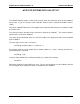
1260-37 User Manual Publication No. 980673-024 Rev. A Control Information for the 1260-37A The following information describes the control-register-to-relay-channel mapping for a 1260-37A Relay Module. This information may be used to control a 1260-37A when using a 1260-01T in the register-based mode of operation.
Publication No. 980673-024 Rev.
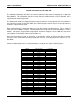
1260-37 User Manual Publication No. 980673-024 Rev. A Control Information for the 1260-37B The following information describes the control-register-to-relay-channel mapping for a 1260-37B Relay Module. This information may be used to control a 1260-37B when using a 1260-01T in the register-based mode of operation. Each relay on this module is controlled by setting or clearing a single bit. Control Registers on the module operate 8 channels simultaneously. There are eight control bits per Control Register.
Publication No. 980673-024 Rev.
60-37 User Manual Publication No. 980673-024 Rev. A This page was left intentionally blank.
Publication No. 980673-024 Rev. A 1260-37 User Manual Table of Contents Chapter 1 ............................................................................................................................ 1-1 MODULE SPECIFICATION .......................................................................................................... 1-1 1260-37 Module Specification ................................................................................................... 1-1 Specifications...................
1260-37 User Manual Publication No. 980673-024 Rev. A Chapter 3 ............................................................................................................................ 3-1 MODULE SPECIFIC SYNTAX ...................................................................................................... 3-1 1260-37 Module Specific Syntax ............................................................................................... 3-1 Syntax .................................................
Publication No. 980673-024 Rev. A 1260-37 User Manual List of Figures Figure 1-1, 1260-37 Switching Card.............................................................................................. 1-1 Figure 3-1, 1260-37 Multiplexer/Scanner Circuit Block Diagram ................................................... 3-7 Figure 3-2, 1260-37 40-Channel SPDT Circuit Block Diagram ...................................................... 3-8 Figure 3-3, 1260-37 Pin Connections ..................................
1260-37 User Manual Publication No. 980673-024 Rev. A List of Tables Table 2-1, 1260-37 Multiplexer/Scanner Circuit Jumper Installation ............................................. 2-3 Table 3-1, 1260-37 Multiplexer/Scanner Circuit Channel Closure .................................................
Publication No. 980673-024 Rev. A 1260-37 User Manual DOCUMENT CHANGE HISTORY Revision A Astronics Test Systems Date Description of Change 01/11/10 Revised per EO 30004. Revised format to current standards. Company name revised throughout manual. Manual now revision letter controlled. Added Document Change History Page v. Back of cover sheet. Revised Warranty Statement, Return of Product, Proprietary Notice and Disclaimer to current standards. (Chap2-1) Unpacking and inspection.
1260-37 User Manual Publication No. 980673-024 Rev. A This page was left intentionally blank.
Publication No. 980673-024 Rev. A 1260-37 User Manual Chapter 1 MODULE SPECIFICATION 1260-37 Module Specification The 1260-37 switch module consists of two switch circuits; a 1 x 48 Signal Multiplexer/Scanner and a 40-Channel SPDT Switch. The Signal Multiplexer circuit switches two lines per channel, and has the capability of being configured as one 1 x 48 multiplexer, two 1 x 24 multiplexers, four 1 x 12 multiplexers, or eight 1 x 6 multiplexers.
1260-37 User Manual Specifications Publication No. 980673-024 Rev. A 1 x 48 Signal Multiplexer/Scanner Switch Configurations Four-wire mode (any configuration) Two-wire mode (any configuration) Maximum Switchable Voltage 250 VDC, 250 VAC RMS (Terminal-Terminal or Terminal-Chassis) Maximum Switchable Current 1A, DC or AC RMS (Per Channel) Maximum Switchable Power (Per Channel) 30 WDC, 62.5 VA AC Path Resistance <0.30Ω (1 x 6 configuration) <0.50Ω (1 x 48 configuration) Isolation Hi-Lo > 7.
Publication No. 980673-024 Rev. A 1260-37 User Manual 40 Channel SPDT Switch Maximum Switchable Voltage 250 VDC, 250 VAC RMS (Terminal-Terminal or Terminal Chassis) Maximum Switchable Current 1 A,DC or AC RMS (Per Channel) Maximum Switchable Power (Per Channel) 30 WDC, 62.5 VA AC Path Resistance <0.5 Ω DC Isolation COM-NO >2x 10⁹ Ω Bandwidth (50Ω termination) >35 MHz Insertion Loss (50Ω termination) <.1 dB to 100kHz <.
1260-37 User Manual Publication No. 980673-024 Rev. A Option 0l 23.1 *A crimp connector kit is also available for this module (P/N 404975-003). A strain relief option can be ordered separately for this crimp connector kit. Ordering Information Safety Module Specification 1-4 Model Number Description Part Number 1260-37 1 x 48 Signal Multiplexer/ Scanner, 40-Channel, SPDT Switch 407353 Refer to the "FOR YOUR SAFETY" page preceding the Table of Contents.
Publication No. 980673-024 Rev. A 1260-37 User Manual Chapter 2 INSTALLATION INSTRUCTIONS Unpacking and Inspection 1. Remove the 1260-37 module and inspect it for damage. If any damage is apparent, inform the carrier immediately. Retain shipping carton and packing material for the carrier’s inspection. 2. Verify that the pieces in the package you received contain the correct 1260-37 module option and the 1260-37 Users Manual. Notify Customer Support if the module appears damaged in any way.
1260-37 User Manual Publication No. 980673-024 Rev. A Module Installation Installation of the 1260-37 Switching Module into a VXIbus mainframe, including the setting of DIP switches, is described in the Installation Section of the 1260 Series VXIbus Switching Cards Manual. Configuration of the motherboard PCB and setting DIP switches S1-5 and S1-6 are described in the following sections.
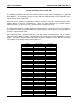
Publication No. 980673-024 Rev. A 1260-37 User Manual Table 2-1, 1260-37 Multiplexer/Scanner Circuit Jumper Installation An X indicates a jumper is to be installed. An (X) indicates the jumper is optional, depending on whether access to the analog bus is required. A blank indicates no jumper is to be installed.
1260-37 User Manual Publication No. 980673-024 Rev. A This page was left intentionally blank.
Publication No. 980673-024 Rev. A 1260-37 User Manual Chapter 3 MODULE SPECIFIC SYNTAX 1260-37 Module Specific Syntax The Module Specific Syntax for the 1260-37 Signal Multiplexer/SPDT Switch is required in the use of the OPEN and CLOSE commands. It will also appear in data output by the Master in response to the PDATAOUT and PSETUP commands. Syntax The Module Specific Syntax for the 1260-37 module is as follows: .
1260-37 User Manual Publication No. 980673-024 Rev. A Note that the SPDT circuit channel number is preceded by a “1” to distinguish it from the Multiplexer/Scanner circuit. For the SPDT circuit, Channels 00 to 39 correspond to channels 100 to 139 in the command syntax. The actual mapping of channel number to connector pins for the Scanner/Multiplexer circuit is given in Table 3-1, and for the SPDT circuit in Figure 3-2. Figure 3-3 shows the physical location of the 64-pin (2 Row) connector pins.
Publication No. 980673-024 Rev. A 1260-37 User Manual The response to the PSETUP command consists of a header on the first line. The header describes the model number, followed by a four-wire or two-wire to indicate the module setup. The next line designates the setup mode for scanning which, by default, is Break-Before-Make (BBM).
1260-37 User Manual Publication No. 980673-024 Rev. A The common output of channel 48 is the single channel of the 96 x I multiplexer, and the 48 HI and 48 LO connections make up the 96 channels. By closing the appropriate channel (0-47) and opening or closing channel 48, a 96 x I multiplexer is achieved. Table 3-1, 1260-37 Multiplexer/Scanner Circuit Channel Closure Channel interconnect for 1, 2 and 4-wire modes.
Publication No. 980673-024 Rev.
1260-37 User Manual Publication No. 980673-024 Rev.
Publication No. 980673-024 Rev.
1260-37 User Manual Publication No. 980673-024 Rev.
Publication No. 980673-024 Rev.
1260-37 User Manual Publication No. 980673-024 Rev. A This page was left intentionally blank.
Publication No. 980673-024 Rev. A 1260-37 User Manual Chapter 4 OPTIONAL HARNESS ASSEMBLIES The following harness assemblies are used to connect 126037 to Freedom Series Test Receiver Interfaces. Each harness documentation consists of an assembly drawing, parts list, system wire list and wire list. 407437 Virginia Panel, Inc. Series VP90 Interface Harness 407438 Harness TTI Testron, Inc.
1260-37 User Manual Publication No. 980673-024 Rev. A This page was left intentionally blank.
A INKSTAMP"J---" APPROXIMATELYWHERESHOWN. APPLYPROTECTIVECOATING (ITEM5) OVERMARKING. MATINGITACONNECTORFOR J100 ANDJ101 ISVIRGINIA PANELP/N510 108 126. USE ITAPINP/N610 110 108. MATINGITACONNECTORFOR J102 ISVIRGINIAPANELP/N 510 108 101. USEITAPIN P/N610 110 108. MARK"407437" ANDLATEST REVISIONONAPPROPRIATE SIZESHRINKTUBINGAPPROXIMATELYWHERESHOWN. PLACEAPPROPRIATESIZECLEAR SHRINKTUBINGOVERMARKING. TERMINATEBRAIDEDSLEEVING (ITEM6) ATINDICATEDENDS WITHBLACKSHRINKTUBING.
1260-37 User Manual Optional Harness Assemblies 4-4 Publication No. 980673-024 Rev.
Publication No. 980673-024 Rev.
1260-37 User Manual Optional Harness Assemblies 4-6 Publication No. 980673-024 Rev.
Publication No. 980673-024 Rev.
1260-37 User Manual Optional Harness Assemblies 4-8 Publication No. 980673-024 Rev.
Publication No. 980673-024 Rev.
1260-37 User Manual Optional Harness Assemblies 4-10 Publication No. 980673-024 Rev.
Publication No. 980673-024 Rev.
A B C D PROPRIETARY NOTICE 10 P2 THRU P8 1 4 A/R 3 2 4 4 REQD 3 INK MARK J1-- PER TABULATION ATP2 THROUGH P8 APPROX. WHERE SHOWN. CABLE # 1 IS SHOWN ON TOP. 2 INK MARK J2-- ATP1 APPROX. WHERE SHOWN. 1. CONNECTOR P2 THRU P8 TO BE FOLDED SO THATPIN # 1 IS ATONE SIDE OF CABLE ONLY AS SHOWN. NOTES: THIS DOCUMENT AND THE TECHNICAL DATA HEREON DISCLOSED ARE PROPRIETARY TO RACAL INSTRUMENTS INC. AND SHALL NOT, WITHOUT THE EXPRESS WRITTEN PERMISSION OF RACAL INSTRUMENTS INC.
Publication No. 980673-024 Rev.
1260-37 User Manual Optional Harness Assemblies 4-14 Publication No. 980673-024 Rev.
Publication No. 980673-024 Rev.
1260-37 User Manual Optional Harness Assemblies 4-16 Publication No. 980673-024 Rev.
Publication No. 980673-024 Rev.
1260-37 User Manual Optional Harness Assemblies 4-18 Publication No. 980673-024 Rev.
Publication No. 980673-024 Rev.
1260-37 User Manual Optional Harness Assemblies 4-20 Publication No. 980673-024 Rev.
Publication No. 980673-024 Rev.
1260-37 User Manual Optional Harness Assemblies 4-22 Publication No. 980673-024 Rev.