
Technical data


1260-37 User Manual Publication No. 980673-024 Rev. A
2 Addendum Page 6/98 Astronics Test Systems
Control Information for the 1260-37A
The following information describes the control-register-to-relay-channel mapping for a 1260-37A
Relay Module. This information may be used to control a 1260-37A when using a 1260-01T in the
register-based mode of operation.
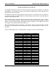
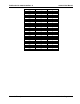
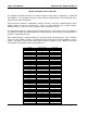
The table below shows the mapping between logical channels used to operate the relay module in
message-based mode and the bits within the Control Registers which may be used to operate the
channel in register-based mode.
Each Control Register is located 2 addresses from the previous Control Register. This is shown in
Table 2-2 of the 1260-01T manual. Control Register 0 is located at the “Base A24 Address” for the
module. Consult the “Register-Based Operation” Section of Chapter 2 of the 1260-01T manual for
a description of calculating control register addresses.
Each channel between 0 and 23 (inclusive) is operated by setting or clearing two bits in parallel.
One bit in each of two different Control Registers must be set to operate these channels as a 4-
wire MUX.
Channels 100 through 139 are each operated by a single bit of a single Control Register.
Channel
Control Register
Control Bit
0
0 and 3
0
1
0 and 3
1
2
0 and 3
2
3
0 and 3
3
4
0 and 3
4
5
0 and 3
5
6
0 and 3
6
7
0 and 3
7
8
1 and 4
0
9
1 and 4
1
10
1 and 4
2
11
1 and 4
3
12
1 and 4
4
13
1 and 4
5
14
1 and 4
6
15
1 and 4
7
16
2 and 5
0
17
2 and 5
1
18
2 and 5
2
19
2 and 5
3
20
2 and 5
4
21
2 and 5
5
22
2 and 5
6
23
2 and 5
7
100
6
0
101
6
1
102
6
2
103
6
3
104
6
4
105
6
5
106
6
6
107
6
7
108
7
0
109
7
1