RACAL INSTRUMENTS™ 1260-43 1260 VXI SWITCHING CARD THREE, 8X24 MATRIX, MODULE Publication No.980673-067 Rev. B Astronics Test Systems Inc. 4 Goodyear, Irvine, CA 92618 Tel: (800) 722-2528, (949) 859-8999; Fax: (949) 859-7139 atsinfo@astronics.com atssales@astronics.com atshelpdesk@astronics.com http://www.astronicstestsystems.com Copyright 2005 by Astronics Test Systems Inc. Printed in the United States of America. All rights reserved.
THANK YOU FOR PURCHASING THIS ASTRONICS TEST SYSTEMS PRODUCT For this product, or any other Astronics Test Systems product that incorporates software drivers, you may access our web site to verify and/or download the latest driver versions. The web address for driver downloads is: http://www.astronicstestsystems.com/support/downloads If you have any questions about software driver downloads or our privacy policy, please contact us at: atsinfo@astronics.
RETURN OF PRODUCT Authorization is required from Astronics Test Systems before you send us your product or sub-assembly for service or calibration. Call or contact Customer Support at 1-800-722-3262 or 1-949-859-8999 or via fax at 1949-859-7139. We can also be reached at: atshelpdesk@astronics.com. If the original packing material is unavailable, ship the product or sub-assembly in an ESD shielding bag and use appropriate packing materials to surround and protect the product.
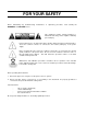
FOR YOUR SAFETY Before undertaking any troubleshooting, maintenance or exploratory procedure, read carefully the WARNINGS and CAUTION notices. This equipment contains voltage hazardous to human life and safety, and is capable of inflicting personal injury. If this instrument is to be powered from the AC line (mains) through an autotransformer, ensure the common connector is connected to the neutral (earth pole) of the power supply.
This page was left intentionally blank.
Publication No. 980673-067 Rev. B 1260-43 User Manual Table of Contents Chapter 1 ........................................................................................................................... 1-1 SPECIFICATIONS ....................................................................................................................... 1-1 Introduction .............................................................................................................................. 1-1 Specifications .
1260-43 User Manual Publication No. 980673-067 Rev. B Chapter 3 ........................................................................................................................... 3-1 MODULE OPERATION ............................................................................................................... 3-1 Operating Modes ...................................................................................................................... 3-1 Operating The 1260-43 in Register-Based Mode .
Publication No. 980673-067 Rev. B 1260-43 User Manual List of Figures Figure 1-1, The 1260-43 .............................................................................................................. 1-2 Figure 2-1, 1260-43, Physical Block Diagram .............................................................................. 2-3 Figure 2-2, 1260-43, Logical Block Diagram ................................................................................ 2-4 Figure 2-3, Front Panel Connector Numbering ..
1260-43 User Manual Publication No. 980673-067 Rev. B List of Tables Table 2-1, 1260-43 Front Panel Pinouts ...................................................................................... 2-6 Table 2-2, Mating Cable Manufactures ...................................................................................... 2-10 Table 3-1, Control/ Status Register Address Offset Assignments ................................................ 3-3 Table 3-2, Control/ Status Register Relay Assignments ...........
Publication No. 980673-067 Rev. B 1260-43 User Manual DOCUMENT CHANGE HISTORY Revision Date Description of Change A 11/16/09 Revised per EO 29965 Revised format to current standards. Company name revised throughout manual. Manual now revision letter controlled. Added Document Change History Page v. Back of cover sheet. Revised Warranty Statement, Return of Product, Proprietary Notice and Disclaimer to current standards. Removed Reshipment Instructions in (Chap. 2-1) and removed (Chap 4). Information.
60-43 User Manual Publication No. 980673-067 Rev. B This page was left intentionally blank.
Publication No. 980673-067 Rev. B 1260-43 User Manual Chapter 1 SPECIFICATIONS Introduction The 1260-43 is an ultra high-density matrix switch card. Each module consists of three 8x24 matrices, which are interconnected via a 10-lane buss. On-board configuration relays allow software control of the matrix configuration. Multiple modules can be linked together via a front panel 10-lane buss to form larger matrices. This allows the user to construct very large Matrices.
1260-43 User Manual Publication No. 980673-067 Rev.
Publication No. 980673-067 Rev.
1260-43 User Manual Publication No. 980673-067 Rev. B Module Capacitance 8 x 24 cfg: 1 x 4 cfg: < 300 pF < 250 pF Note: When using expansion buss in configuration, add an additional 50 pF Impedance 50 Ohms @ 5 MHz Noise Floor (100Hz B/W, 0 to 10 MHz) Leakage to Ground < -100dbm > 100 MΩ Impulse Withstanding Voltage > 100 Vrms Insulation resistance > 109 Ω Relay Settling Time < 10 ms Shock 30g, 11 ms, ½ sine wave Vibration 0.013 in. P-P, 5-55 Hz Bench Handling 4 in.
Publication No. 980673-067 Rev. B Ordering Information 1260-43 User Manual Listed below are part numbers for the 1260-43 switch module. The 1260-43 uses an IDC type of mating connector.
1260-43 User Manual Publication No. 980673-067 Rev. B This page was left intentionally blank.
Publication No. 980673-067 Rev. B 1260-43 User Manual Chapter 2 INSTALLATION INSTRUCTIONS Unpacking and Inspection 1. Remove the 1260-43 module and inspect it for damage. If any damage is apparent, inform the carrier immediately. Retain shipping carton and packing material for the carrier’s inspection. 2. Verify that the pieces in the package you received contain the correct 1260-43 module option and the 1260-43 Users Manual. Notify Customer Service if the module appears damaged in any way.
1260-43 User Manual Module Configuration Publication No. 980673-067 Rev. B The 1260-43 is an ultra high-density matrix switch card. Each module consists of three 8x24, single wire matrices, which are interconnected via a 10-lane buss. On-board configuration relays allow software control of the matrix configuration. The 1260-43 is comprised of three boards, the 405237, 405249 and the 405250.
Publication No. 980673-067 Rev. B 1260-43 User Manual For a block diagram of the 1260-43, refer to both Figure 2-1 and Figure 2-2.
1260-43 User Manual Publication No. 980673-067 Rev.
Publication No. 980673-067 Rev. B 1260-43 User Manual The 1260-43 has six 34-pin front-panel connectors, labeled J200J205 and two 20-pin connectors, labeled J206 and J207. Each matrix consists of a pair of 34-pin connectors. The two 20-pin connectors are used for bussing the 10-lane buss in and out of the 1260-43. The output of the 10-lane buss that connects to J207 incorporates a 3-bit shift to the right.
1260-43 User Manual Publication No. 980673-067 Rev.
Publication No. 980673-067 Rev.
1260-43 User Manual Publication No. 980673-067 Rev.
Publication No. 980673-067 Rev.
1260-43 User Manual Publication No. 980673-067 Rev. B The front panel connectors are a standard IDC type of connector. The mating connectors are unique due to the coax cabling. Special manufacturing processes are required in joining the coax cable to the mating connector. This prohibits manufactures from selling Individual connector parts. Only finished cable assemblies are sold. Mating cable/connector assemblies are available from Joy Signal, Molex and 3M.
Publication No. 980673-067 Rev. B More About Maximum Current Ratings 1260-43 User Manual The front panel connector and pins are rated for 2 A per pin, with all channels conducting full-rated current. The relays are rated at 2 A. This keeps the temperature rise within 10°C. Definitions: • Max current carrying capacity The maximum current that the relay can conduct if the relay is not switched while voltage is applied.
1260-43 User Manual Publication No. 980673-067 Rev. B This page was left intentionally blank.
Publication No. 980673-067 Rev. B 1260-43 User Manual Chapter 3 MODULE OPERATION Operating Modes The 1260-43 is operated in register-based mode. In the register-based mode, the user writes directly to the control registers on the 1260-43 module. The 1260-01T command module does not monitor these operations, and does not keep track of the relay states on the 1260-43 module in this mode. A conceptual view of the register-based mode is shown in Figure 3-1 below.
1260-43 User Manual Publication No. 980673-067 Rev. B matrices (refer to Appendix A.) With the exception of the matrix output relay groups, each group of relays operating on the buss is comprised of 10 relays. The matrix output relay groups only operate on 5 of the 10 signals of the buss and thus have only one control/status register associated with each group. For the rest of the relay groups an A and B control/status register pair is assigned to each group. Only bits 4-0 of the register are used.
Publication No. 980673-067 Rev. B 1260-43 User Manual 205801 Control Register 0 205803 Control Register 1 Table 3-1 shows the address offset assignments for each Control/Status register while Table 3-2 shows the Control/Status Register Relay / Buss Assignments. Refer to Appendix A and B in determining relay groups and the relay reference designations. Table 3-1, Control/ Status Register Address Offset Assignments Control/Status Address Function Reg.
1260-43 User Manual Publication No. 980673-067 Rev. B Reg. 10B 02B Matrix Bus ‘B’ Stub Break 1 (upper bus bits 9-5) Reg. 11A 02D Matrix Bus ‘B’ Stub Break 2 (lower bus bits 4-0) Reg. 11B 02F Matrix Bus ‘B’ Stub Break 2 (upper bus bits 9-5) Reg. 12A 031 Matrix Bus ‘B’ Stub Break 3 (lower bus bits 4-0) Reg. 12B 033 Matrix Bus ‘B’ Stub Break 3 (upper bus bits 9-5) Reserved 035-03F Reg. 13A 041 Matrix Bus ‘B’ Stub Break 4 (lower bus bits 4-0) Reg.
Publication No. 980673-067 Rev. B 1260-43 User Manual Reg. 25A 071 Matrix Bus ‘B’ Load 2 Connection (lower bus bits 4-0) Reg. 25B 073 Matrix Bus ‘B’ Load 2 Connection (upper bus bits 9-5) Reserved 075-07F Reg. 26A 081 Matrix Bus ‘C’ Pull-up/Pull-down for Load 1 Reg. 26B 083 Matrix Bus ‘C’ Pull-up/Pull-down for Load 2 Reg. 27A 085 Matrix Bus ‘C’ Resistor Selection for Load 1 Reg. 27B 087 Matrix Bus ‘C’ Resistor Selection for Load 2 Reg.
1260-43 User Manual Publication No. 980673-067 Rev. B Reg. 40 0C1 Matrix Bus ‘A’ Output 3 Reg. 41 0C3 Matrix Bus ‘A’ Output 4 Reg. 42 0C5 Matrix Bus ‘A’ Output 5 Reg. 43 0C7 Matrix Bus ‘A’ Output 6 Reg. 44 0C9 Matrix Bus ‘A’ Output 7 Reg. 45 0CB Matrix Bus ‘A’ Output 8 Reg. 46 0CD Matrix Bus ‘A’ Output 9 Reg. 47 0CF Matrix Bus ‘A’ Output 10 Reg. 48 0D1 Matrix Bus ‘A’ Output 11 Reg. 49 0D3 Matrix Bus ‘A’ Output 12 Reg. 50 0D5 Matrix Bus ‘A’ Output 13 Reg.
Publication No. 980673-067 Rev. B 1260-43 User Manual Reg. 65B 107 Matrix Bus ‘B’ Instrument Input 4 (upper bus bits 9-5) Reg. 66A 109 Matrix Bus ‘B’ Instrument Input 5 (lower bus bits 4-0) Reg. 66B 10B Matrix Bus ‘B’ Instrument Input 5 (upper bus bits 9-5) Reg. 67A 10D Matrix Bus ‘B’ Instrument Input 6 (lower bus bits 4-0) Reg. 67B 10F Matrix Bus ‘B’ Instrument Input 6 (upper bus bits 9-5) Reg. 68A 111 Matrix Bus ‘B’ Instrument Input 7 (lower bus bits 4-0) Reg.
1260-43 User Manual Publication No. 980673-067 Rev. B Reg. 90 14D Matrix Bus ‘B’ Output 21 Reg. 91 14F Matrix Bus ‘B’ Output 22 Reg. 92 151 Matrix Bus ‘B’ Output 23 Reg. 93 153 Matrix Bus ‘B’ Output 24 Reg. 94A 155 Matrix Bus ‘C’ Instrument Input 1 (lower bus bits 4-0) Reg. 94B 157 Matrix Bus ‘C’ Instrument Input 1 (upper bus bits 9-5) Reg. 95A 159 Matrix Bus ‘C’ Instrument Input 2 (lower bus bits 4-0) Reg. 95B 15B Matrix Bus ‘C’ Instrument Input 2 (upper bus bits 9-5) Reg.
Publication No. 980673-067 Rev. B 1260-43 User Manual Reg. 111 193 Matrix Bus ‘C’ Output 10 Reg. 112 195 Matrix Bus ‘C’ Output 11 Reg. 113 197 Matrix Bus ‘C’ Output 12 Reg. 114 199 Matrix Bus ‘C’ Output 13 Reg. 115 19B Matrix Bus ‘C’ Output 14 Reg. 116 19D Matrix Bus ‘C’ Output 15 Reg. 117 19F Matrix Bus ‘C’ Output 16 Reg. 118 1A1 Matrix Bus ‘C’ Output 17 Reg. 119 1A3 Matrix Bus ‘C’ Output 18 Reg. 120 1A5 Matrix Bus ‘C’ Output 19 Reg. 121 1A7 Matrix Bus ‘C’ Output 20 Reg.
1260-43 User Manual Publication No. 980673-067 Rev. B Table 3-2, Control/ Status Register Relay Assignments Control/ Status Register Reg. 00A Control/ Status Register Reg. 00B Control/ Status Register Reg. 01A Control/ Status Register Reg. 01B Control/ Status Register Reg.
Publication No. 980673-067 Rev. B Control/ Status Register Reg. 02B Control/ Status Register Reg. 03A Control/ Status Register Reg. 03B Control/ Status Register Reg. 04A Control/ Status Register Reg.
1260-43 User Manual Control/ Status Register Reg. 05A Control/ Status Register Reg. 05B Control/ Status Register Reg. 06A Control/ Status Register Reg. 06B Control/ Status Register Reg. 07A Publication No. 980673-067 Rev.
Publication No. 980673-067 Rev. B Control/ Status Register Reg. 07B Control/ Status Register Reg. 08A Control/ Status Register Reg. 08B Control/ Status Register Reg. 09A Control/ Status Register Reg.
1260-43 User Manual Control/ Status Register Reg. 10A Control/ Status Register Reg. 10B Control/ Status Register Reg. 11A Control/ Status Register Reg. 11B Control/ Status Register Reg. 12A Publication No. 980673-067 Rev.
Publication No. 980673-067 Rev. B Control/ Status Register Reg. 12B Control/ Status Register Reg. 13A Control/ Status Register Reg. 13B Control/ Status Register Reg. 14A Control/ Status Register Reg.
1260-43 User Manual Control/ Status Register Reg. 15A Control/ Status Register Reg. 15B Control/ Status Register Reg. 16A Control/ Status Register Reg. 16B Control/ Status Register Reg. 17A Publication No. 980673-067 Rev.
Publication No. 980673-067 Rev. B Control/ Status Register Reg. 17B Control/ Status Register Reg. 18A Control/ Status Register Reg. 18B Control/ Status Register Reg. 19A Control/ Status Register Reg.
1260-43 User Manual Control/ Status Register Reg. 20A Control/ Status Register Reg. 20B Control/ Status Register Reg. 21A Control/ Status Register Reg. 21B Control/ Status Register Reg. 22A Publication No. 980673-067 Rev.
Publication No. 980673-067 Rev. B Control/ Status Register Reg. 22B Control/ Status Register Reg. 23A Control/ Status Register Reg. 23B Control/ Status Register Reg. 24A Control/ Status Register Reg.
1260-43 User Manual Control/ Status Register Reg. 25A Control/ Status Register Reg. 25B Control/ Status Register Reg. 26A Control/ Status Register Reg. 26B Control/ Status Register Reg. 27A Publication No. 980673-067 Rev.
Publication No. 980673-067 Rev. B Control/ Status Register Reg. 27B Control/ Status Register Reg. 28A Control/ Status Register Reg. 28B Control/ Status Register Reg. 29A Control/ Status Register Reg.
1260-43 User Manual Control/ Status Register Reg. 30A Control/ Status Register Reg. 30B Control/ Status Register Reg. 31A Control/ Status Register Reg. 31B Control/ Status Register Reg. 32A Publication No. 980673-067 Rev.
Publication No. 980673-067 Rev. B Control/ Status Register Reg. 32B Control/ Status Register Reg. 33A Control/ Status Register Reg. 33B Control/ Status Register Reg. 34A Control/ Status Register Reg.
1260-43 User Manual Control/ Status Register Reg. 35A Control/ Status Register Reg. 35B Control/ Status Register Reg. 36A Control/ Status Register Reg. 36B Control/ Status Register Reg. 37A Publication No. 980673-067 Rev.
Publication No. 980673-067 Rev. B Control/ Status Register Reg. 37B Control/ Status Register Reg. 38 Control/ Status Register Reg. 39 Control/ Status Register Reg. 40 Control/ Status Register Reg.
1260-43 User Manual Control/ Status Register Reg. 42 Control/ Status Register Reg. 43 Control/ Status Register Reg. 44 Control/ Status Register Reg. 45 Control/ Status Register Reg. 46 Publication No. 980673-067 Rev.
Publication No. 980673-067 Rev. B Control/ Status Register Reg. 47 Control/ Status Register Reg. 48 Control/ Status Register Reg. 49 Control/ Status Register Reg. 50 Control/ Status Register Reg.
1260-43 User Manual Control/ Status Register Reg. 52 Control/ Status Register Reg. 53 Control/ Status Register Reg. 54 Control/ Status Register Reg. 55 Control/ Status Register Reg. 56 Publication No. 980673-067 Rev.
Publication No. 980673-067 Rev. B Control/ Status Register Reg. 57 Control/ Status Register Reg. 58 Control/ Status Register Reg. 59 Control/ Status Register Reg. 60 Control/ Status Register Reg.
1260-43 User Manual Control/ Status Register Reg. 62A Control/ Status Register Reg. 62B Control/ Status Register Reg. 63A Control/ Status Register Reg. 63B Control/ Status Register Reg. 64A Publication No. 980673-067 Rev.
Publication No. 980673-067 Rev. B Control/ Status Register Reg. 64B Control/ Status Register Reg. 65A Control/ Status Register Reg. 65B Control/ Status Register Reg. 66A Control/ Status Register Reg.
1260-43 User Manual Control/ Status Register Reg. 67A Control/ Status Register Reg. 67B Control/ Status Register Reg. 68A Control/ Status Register Reg. 68B Control/ Status Register Reg. 69A Publication No. 980673-067 Rev.
Publication No. 980673-067 Rev. B Control/ Status Register Reg. 69B Control/ Status Register Reg. 70 Control/ Status Register Reg. 71 Control/ Status Register Reg. 72 Control/ Status Register Reg.
1260-43 User Manual Control/ Status Register Reg. 74 Control/ Status Register Reg. 75 Control/ Status Register Reg. 76 Control/ Status Register Reg. 77 Control/ Status Register Reg. 78 Publication No. 980673-067 Rev.
Publication No. 980673-067 Rev. B Control/ Status Register Reg. 79 Control/ Status Register Reg. 80 Control/ Status Register Reg. 81 Control/ Status Register Reg. 82 Control/ Status Register Reg.
1260-43 User Manual Control/ Status Register Reg. 84 Control/ Status Register Reg. 85 Control/ Status Register Reg. 86 Control/ Status Register Reg. 87 Control/ Status Register Reg. 88 Publication No. 980673-067 Rev.
Publication No. 980673-067 Rev. B Control/ Status Register Reg. 89 Control/ Status Register Reg. 90 Control/ Status Register Reg. 91 Control/ Status Register Reg. 92 Control/ Status Register Reg.
1260-43 User Manual Control/ Status Register Reg. 94A Control/ Status Register Reg. 94B Control/ Status Register Reg. 95A Control/ Status Register Reg. 95B Control/ Status Register Reg. 96A Publication No. 980673-067 Rev.
Publication No. 980673-067 Rev. B Control/ Status Register Reg. 96B Control/ Status Register Reg. 97A Control/ Status Register Reg. 97B Control/ Status Register Reg. 98A Control/ Status Register Reg.
1260-43 User Manual Control/ Status Register Reg. 99A Control/ Status Register Reg. 99B Control/ Status Register Reg. 100A Control/ Status Register Reg. 100B Control/ Status Register Reg. 101A Publication No. 980673-067 Rev.
Publication No. 980673-067 Rev. B Control/ Status Register Reg. 101B Control/ Status Register Reg. 102 Control/ Status Register Reg. 103 Control/ Status Register Reg. 104 Control/ Status Register Reg.
1260-43 User Manual Control/ Status Register Reg. 106 Control/ Status Register Reg. 107 Control/ Status Register Reg. 108 Control/ Status Register Reg. 109 Control/ Status Register Reg. 110 Publication No. 980673-067 Rev.
Publication No. 980673-067 Rev. B Control/ Status Register Reg. 111 Control/ Status Register Reg. 112 Control/ Status Register Reg. 113 Control/ Status Register Reg. 114 Control/ Status Register Reg.
1260-43 User Manual Control/ Status Register Reg. 116 Control/ Status Register Reg. 117 Control/ Status Register Reg. 118 Control/ Status Register Reg. 119 Control/ Status Register Reg. 120 Publication No. 980673-067 Rev.
Publication No. 980673-067 Rev. B Control/ Status Register Reg. 121 Control/ Status Register Reg. 122 Control/ Status Register Reg. 123 Control/ Status Register Reg. 124 Control/ Status Register Reg.
1260-43 User Manual Publication No. 980673-067 Rev. B Matrix Load Configuration Each matrix has two loads that can be configured as a pull-up or pull-down. Each load has 5 relay pairs used to select the load value and set it as a pull-up or pull-down. The two loads can be used in conjunction to form a pull-up/pull-down load. Once configured, each load can be tied to one of the ten buss signals. This is accomplished using 10 relays, one for each buss signal.
Publication No. 980673-067 Rev.
1260-43 User Manual Publication No. 980673-067 Rev.
Publication No. 980673-067 Rev.
1260-43 User Manual Logical Relay Layout A-2 Publication No. 980673-067 Rev.
Publication No. 980673-067 Rev.
1260-43 User Manual Publication No. 980673-067 Rev. B This page was left intentionally blank.
Publication No. 980673-067 Rev.
1260-43 User Manual 1260-43 Relay Layout B-2 Publication No. 980673-067 Rev.