-866-207-6631 | www.rackmountsolutions.net sales@rackmountsolutions.
English Enterprise 1U Rackmount Series User's Manual 1. Introduction 2 2. Controls and Indicators 6 3. Installation 8 4. Operation 12 5. Troubleshooting 15 6. Replacing the Battery 16 7. Obtaining Service 19 8. Specifications 20 9. Configurable Parameters & Settings 22 10. Limited Product Warranty 23 11. Declaration of Conformity 25 © Copyright Para Systems, Inc.
English Thank you for purchasing a MINUTEMAN power protection product. It has been designed and manufactured to provide many years of trouble free service.
This symbol indicates "Equipment Grounding Conductor" CAUTION! Connect the UPS to a two pole, three wire grounding AC wall outlet. The receptacle must be connected to the appropriate branch protection (circuit breaker or fuse). Connection to any other type of receptacle may result in a shock hazard and violate local electrical codes. Do not use extension cords, adapter plugs, or surge strips.
English NOTICE: This equipment has been tested and found to comply with the limits for a Class A computing device in accordance with the specifications in Subpart J of Part 15 of FCC Rules and the Class A limits for radio noise emissions from digital apparatus set out in the Radio Interference of the Canadian Department of Communications. These limits are designed to provide reasonable protection against such interference in a residential installation.
As a general policy, Para Systems Inc. (Para Systems) does not recommend the use of any of its products in life support applications where failure or malfunction of the Para Systems product can be reasonably expected to cause failure of the life support device or to significantly affect its safety or effectiveness. Para Systems does not recommend the use of any of its products in direct patient care.
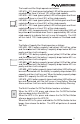
English CONTROL PANEL The AC normal (green) LED illuminates in a steady state when the UPS is on and operating in the AC normal mode. The AC normal LED will extinguish when operating in the Battery mode. The On-Battery (green) LED illuminates in a steady state when the UPS is operating in the Battery mode. The On-Battery LED will extinguish when operating in the AC normal, Boost and Buck modes. The Boost (yellow) LED illuminates in a blinking state when the UPS is operating in the Boost mode.
The Battery Capacity Bar Graph operates as follows: LED #90: >90% battery capacity (red/yellow) LED will be yellow and illuminated until the battery’s capacity drops below 80% capacity and then it will extinguish. LED #70: >70% battery capacity (green/yellow) LED will be yellow and illuminated until the battery’s capacity drops below 60% capacity and then it will extinguish.
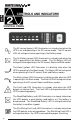
REAR PANEL English 1. The input power cord has a NEMA 5-15P Plug. 2. The input circuit breaker will trip in the event the load exceeds the UPS’s power rating. 3. The Battery Backup output power receptacles are NEMA 5-15R type. The output receptacles are electrically wired into two segments to support the "Load Shedding Function". The three receptacles on the left are Segment 1 and the three receptacles on the right are Segment 2. 4. The RS232 Communications Interface Port is for UPS monitoring and control.
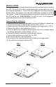
Be sure to read the installation placement and all the cautions before installing the UPS. Place the UPS in the final desired location and complete the rest of the installation procedure. These UPSs are shipped with the internal batteries disconnected. The batteries must be connected before putting these UPSs into service. Follow the procedure below to connect the batteries and install the UPS into the rack. USE CAUTION: The UPS is heavy. Use the appropriate number of personnel when installing the UPS.
Installing the UPS in a 4-post rack English USE CAUTION: The UPS is heavy. Use the appropriate number of personnel when installing the UPS. 1. Install the rails in the 4-post rack. (FIG. 1) 2. Install the rack ears on the UPS. (FIG. 2) 3. Align the cleats with the rails and slide the UPS into the rails. (FIG. 3) NOTE: The cleats are pre-mounted on the UPS. 4. Secure the UPS to the rack with the retaining screws (not provided). The UPS is ready for normal operation, see connecting your equipment.
Plug the equipment into the output receptacles on the rear panel of the UPS. Do not use extension cords, adapter plugs or surge strips on the output of the UPS. Ensure that you do not exceed the maximum output rating of the UPS (refer to the information label on the UPS or the Electrical Specifications in this manual). CAUTION! DO NOT connect a laser printer to the output receptacles on the UPS, unless the UPS is rated 2000VA or greater.
English SYSTEM OVERVIEW This Line-Interactive 1U Rackmount model UPS protects internetworking and telecommunications equipment from blackouts, brownouts, overvoltages, and surges. The AVR function continuously corrects the voltages, in-between the brownout and overvoltage transfer points (85 - 150VAC), to a safe usable level. When the UPS is operating in the AVR mode the audible alarm will remain silent and the Boost or the Buck indicator will blink.
DIP SWITCH SETTINGS The DIP Switch setting may be changed by the user to set the desired Inverter (On-Battery) output voltage. The DIP Switch must be set to the desired Inverter (On-Battery) output voltage and then the UPS must be turned off and restarted to reconfigure the microprocessor and save the changes. The Inverter (OnBattery) output voltage setting can be either 120VAC (default) or 127VAC.
English OVERLOAD When the amount of load attached to the UPS exceeds its power rating, the Overload LED will illuminate and the UPS will sound a constant alarm. This alarm will remain on until the excess load is removed or the UPS’s self protection circuit shuts the UPS down. WEAK/BAD BATTERY The UPS automatically tests the battery’s condition and will illuminate the Weak/ Bad Battery LED and sound the alarm. This alarm will be repeated until the batteries pass a self test.
English Symptom Possible Cause UPS will not turn on On/Off/Test button not pushed UPS operates in Input AC circuit breaker is battery mode only, tripped even though there is normal AC present Fault LED is illuminated Site Wiring Fault LED is illuminated The AC normal LED is illuminated, but there is no output UPS has detected an internal fault Incorrect service wiring UPS does not provide expected runtime The batteries may be weak or at the end of useful service life The UPS is being controlled via i
English REPLACING THE BATTERY (QUALIFIED SERVICE PERSONNEL ONLY) The Enterprise 1U Rackmount Series UPS has an easy to replace hot-swappable batteries. Please read all of the WARNINGS and CAUTIONS before attempting to service the batteries. NOTE: If there is a power interruption while replacing the hot-swappable batteries, with the UPS on, the load will not be backed up. WARNING! This Uninterruptible Power Supply contains potentially hazardous voltages.
Model # Battery Qty/Rating EPOWER Part # Panasonic Part # CSB Part # Yuasa Part # E700RM1U E1000RM1U E1500RM1U 4-6V9Ah 4-6V9Ah 4-6V9Ah HR9-6 HR9-6 HR9-6 UP-RW0645Ch1 UP-RW0645Ch1 UP-RW0645Ch1 HRL634WF2FR HRL634WF2FR HRL634WF2FR VALA NPW 45-6 VALA NPW 45-6 VALA NPW 45-6 BATTERY REPLACEMENT PROCEDURE PLEASE READ THE CAUTIONS AND WARNINGS BEFORE ATTEMPTING TO REPLACE THE BATTERIES Hot-swappable batteries mean that the batteries can be replaced without powering down the whole UPS system.
English 8. Remove the four retaining screws for the battery retaining bracket. (FIG. 3) 9. Remove the battery retaining bracket. (FIG. 3) 10. Grasp the battery tray and gently pull the battery tray out far enough to get to the battery connectors (red and black). (FIG. 4) 11. Disconnect the battery connectors (red and black). (FIG. 5) 12. Gently remove the battery tray from the UPS and set on the floor. NOTE: Use Caution, the battery tray is heavy. 13. Remove the battery jumper wires. 14.
English IF THE UPS REQUIRES SERVICE 1.Use the TROUBLESHOOTING section to eliminate obvious causes. 2.Verify there are no circuit breakers tripped. A tripped circuit breaker is the most common problem. 3.Call your dealer for assistance. If you cannot reach your dealer, or if they cannot resolve the problem call or fax MINUTEMAN Technical Support at the following numbers; Voice phone (972) 446-7363, FAX line (972) 446-9011 or visit our Web site at www.minutemanups.com the "Discussion Board".
English SYSTEM SPECIFICATIONS E700RM1U Model Number E1000RM1U E1500RM1U Line-Interactive, Sine Wave Topology Maximum Power Capacity 1000VA 700W 700VA 490W 1500VA 900W INPUT Number of Phase Single (1∅ 2W +G) Nominal Voltage 120VAC Acceptable Input voltage 0 - 165VAC Voltage Range 85 - 150VAC Frequency Limits 50 or 60 Hz, +/-6Hz, autosensing Low Voltage Transfer Point 85V resets to Utility Power at 90V or higher High Voltage Transfer Point 150V resets to Utility Power at 145V or lower
BATTERY SYSTEM Battery Type Typical Recharge Time 8 hours from total discharge Typical Battery Life 3-5 years, depending on discharge cycles and ambient temp System Voltage 24VDC 24VDC Battery Quantity/Rating 24VDC 4-6V9Ah 4-6V9Ah 4-6V9Ah Runtime: Half Load 13-Minutes 9-Minutes 7-Minutes Runtime: Full Load 6-Minutes 4-Minutes 3-Minutes SURGE PROTECTION AND FILTERING 800 J Surge energy rating 6500 Amps total Surge current capability Surge response time 0 ns (instantaneous) normal mode
English (These items may require optional software or hardware) User Choices Factory Default UPS ID Enterprise 1U Up to 64 RM Series characters to define the UPS Date of battery Battery Date of manufacture replacement install month/day/year date XX/XX/XXXX Up to 5 Battery 1826 characters life in days Function Description Use this function to uniquely identify the UPS in your network configuration Enter the current date when replacing batteries At first battery replacement, reset to reflect actual number
English Para Systems Inc. (Para Systems) warrants this equipment, when properly applied and operated within specified conditions, against faulty materials or workmanship for a period of three years from the date of purchase. For equipment sites within the United States and Canada, this warranty covers repair or replacement of defective equipment at the discretion of Para Systems. Repair will be from the nearest authorized service center. Replacement parts and warranty labor will be borne by Para Systems.
LIMITED PRODUCT WARRANTY (Continued) English EXCEPT AS PROVIDED ABOVE, IN NO EVENT WILL PARA SYSTEMS BE LIABLE FOR DIRECT, INDIRECT, SPECIAL, INCIDENTAL, OR CONSEQUENTIAL DAMAGES ARISING OUT OF THE USE OF THIS PRODUCT, EVEN IF ADVISED OF THE POSSIBILITY OF SUCH DAMAGE. Specifically, Para Systems is not liable for any costs, such as lost profits or revenue, loss of equipment, loss of use of equipment, loss of software, loss of data, cost of substitutes, claims by third parties, or otherwise.
English DECLARATION OF CONFORMITY Application of Council Directive(s): 89/336/EEC, 73/23/EEC Standard(s) to which Conformity is declared: EN55022, EN55024 EN61000-6-1, EN61000-6-3 EN61000-4-5 Manufacturer’s Name: Para Systems, Inc.
Notes: English 26
Para Systems, Inc. 1455 Lemay Dr. Carrollton, TX 75007 Phone: 1-972-446-7363 Fax: 1-972-446-9011 Internet: minutemanups.com UPS Sizing: sizemyups.com PN - 34000256 Rev.