Active and E-Series Uninterruptible Power Supply Operating Manual • 700 VA • 700 VA Rackmount • 1000 VA • 1000 VA Rackmount • 2000 VA • 2000 VA Rackmount • 3000 VA • 3000 VA Rackmount • 6000 VA • 10000 VA • 20000 VA
Active™ and E-Series™ User Instruction Manual IMPORTANT SAFETY INSTRUCTIONS SAVE THESE INSTRUCTIONS. Please read and save these instructions.
Chapter 1 Chloride Introduction . . . . . . . . . . . . . . . . . . . . . . . . . . . . . . . . . . . . . . . . . . . . . . .1 Registering your Chloride Active UPS . . . . . . . . . . . . . . . . . . . . . . . . . . . . . . . . . . . . . . . . . . . . . . . . . . . . 1 Technical Support and Service (Active) . . . . . . . . . . . . . . . . . . . . . . . . . . . . . . . . . . . . . . . . . . . . . . . . . . . 1 Safety Notes . . . . . . . . . . . . . . . . . . . . . . . . . . . . . . . . . . . . . . . . . . .
Commissioning of an External Battery Cabinet . . . . . . . . . . . . . . . . . . . . . . . . . . . . . . . . . . . . . . . . . . . . 39 Chapter 14 Operational Characteristics (E-Series) . . . . . . . . . . . . . . . . . . . . . . . . . . . . . . .41 Ready for Operation Check . . . . . . . . . . . . . . . . . . . . . . . . . . . . . . . . . . . . . . . . . . . . . . . . . . . . . . . . . . . 41 Self Test . . . . . . . . . . . . . . . . . . . . . . . . . . . . . . . . . . . . . . . . . . . . . . . . . . . .
Chapter 1 Chloride Introduction Thank you for selecting this uninterruptible power supply (UPS). Chloride’s Active UPS offers the most reliable protection from the harmful effects of electrical line disturbances for your computing and communications equipment. 1.1 Registering your Chloride Active UPS To ensure that your Active model and serial number are registered, complete and mail the enclosed postagepaid warranty card. 1.
• Transport the unit only in suitable packaging (protect against jolts and shocks). • If the equipment is moved indoors from a cold environment, condensation may occur. Before you place the equipment in service it must be absolutely dry. An acclimatization period of at least two hours is required. • This equipment must be installed in an indoor, temperature controlled environment that is free of conductive contaminants.
Chapter 2 Display and Operation Elements (Active) The Uninterruptible Power System (UPS) is connected between AC power and the load. It protects the load against mains disturbances, especially power failures. Its operation is based on the on-line principle. The connected load is supplied power through the UPS’s inverter. Power disturbances from the mains are suppressed which increases the loads’ operational security (PC, network server, multi-user systems etc.
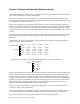
2.1 Front The OVERLOAD indicator is on when the UPS is overloaded. The LED-chain LOAD indicates the load state of the UPS. The BYPASS indicator is on when the UPS supplies a voltage via the bypass. The INVERTER indicator is on when the inverter is in operation. The LED-chain BATTERY indicates the battery’s charge state (normal operation) or the % of battery time remaining when mains fail. The LINE indicator is on when there is mains voltage at the UPS input. The ALARM indicator is on when the UPS is faulty.
2.2 Rear 2.2.1 Active 700 and 1000 Selector switch - for output voltage. The selection of the output voltage must be made with the UPS switched off and unplugged.* Selector switch Interface COM A Interface COM B (optional) Fan Input fuse - the fuse may only be changed when the device is switched off and unplugged. Input fuse Mains connection Output receptacles Fig. 1: Active 700 Rear View Selector switch - for output voltage.
2.2.2 Active 2000 and 3000 Selector switch Interface COM A Interface COM B (optional) Selector switch - for output voltage. The selection of the output voltage must be made with the UPS switched off and unplugged.* Connection for additional batteries Fans Output Receptacle Output Receptacle Fuses Input circuit breaker Linecord Output receptacles Fig.
Chapter 3 Active Rackmount Series The technical data of the Active Rackmount UPS corresponds to the standard unit series Active, except for the details which are explained below. The Active Rackmount consists of the following types: • Active700-19, with 700 VA nominal rating • Active1000-19, with 1000 VA nominal rating • Active2000-19, with 2000 VA nominal rating • Active3000-19, with 3000 VA nominal rating, • BPActive1000-19 • BPActive3000-19 The above listed units with a mounting height of 2 U (2 U = 3.
3.2.2 Mechanical Attachment The units must be attached in the rack on both sides. When using the attached mounting rails, the single unit can easily be inserted into a 2 U mounting space or removed from it. In order to attach the unit in the horizontal position, the front-plate has to be attached to the 19-inch rack at the indicated points on both sides of the unit. Do not attach the unit only at the front-plate. This may damage the unit and/or other mounted units. Fig.
3.3 Unit Rear View and Connections 3.3.1 Active 700-19 and Active 1000-19 The following figures show the Active700-19, Active1000-19, Active2000-19 and Active 3000-19 with battery extensions. NOTE: No battery extension can be connected to the 700 VA unit. Fig. 6: Active700-19 Fig. 7: Active1000-19 Fig. 8: Battery Pack - BPActive1000-19 To connect the battery pack to the unit, use the separate cable supplied.
3.3.2 Active 2000-19 and Active 3000-19 NOTE: Each battery cabinet BPActive3000-19 contains two battery connections. The first battery pack is connected to the battery cables of the UPS, each further extension is connected by means of the two cables. Each cable is non-interchangeable, because the sockets are coded. Fig. 9: Active2000-19 Fig. 10: Battery Pack - BPActive3000-19 3.3.3 Active3000-19 Fig. 11: Active3000-19 Fig.
Chapter 4 Active Installation and Commissioning Upon receipt of your UPS, carefully examine the packing containers for any sign of physical damage. Notify the carrier immediately if damage is present. Carefully unpack the UPS. Retain the packaging for reuse or disposal. NOTE: If damages are detected, please inform the shipping agent immediately.
4.1 Commissioning of an External Battery Cabinet The following table shows the designations of the battery cabinets which are available for the UPS devices. Table 2. External Battery Packs Model Cabinet Batteries Active 700 NA NA Active 1000 BPActive1000-19 2x (3 x 7. 2 Ah) Active 2000 BPActive3000-19 2x (8 x 7. 2 Ah) Active 3000 BPActive3000-19 2x (8 x 7. 2 Ah) Disconnect the UPS from the mains and the loads from the UPS.
Chapter 5 Operational Characteristics (Active) 5.1 Ready for Operation Check To check the emergency supply feature of the UPS, it must be disconnected from the mains. When correctly functioning with charged batteries, an acoustical signal in intervals of 4 seconds will be heard. The LED “LINE” (line voltage) indicator disappears. When the interval between the acoustical signals is reduced to 1 second, the UPS will supply energy for a maximum of 3 more minutes before it is automatically switched off.
5.3 Modes of Operation There are three modes of operation, when the UPS is switched on. 5.3.1 Normal Operation, Inverter On (Mains Available) Lights Illuminated Fig. 14: Front Display Panel During Normal Operations (Mains Available) The loads are supplied through the inverter, the energy is taken from the mains. 5.3.2 Battery Operation, Inverter On (Mains Failure) Lights Illuminated During Power Failure Fig.
5.3.3 Bypass Operation, Inverter OFF (Overload > 140%) Lights Illuminated in BYPASS Operation Fig. 16: Front Display Panel During Bypass Operation (Overload > 140%) In the event of large overload (> 140%) switch-over to bypass is initiated and the inverter is blocked. The energy is taken from the mains. This is not a normal operating status. In the event of mains failure the loads will no longer be supplied (no UPS operation).
Chapter 6 Description of the Interface (Active) The Active UPS has a standard interface COM A and an optional interface COM B. Protocol data transfer signal exchange is through COM A RS232 interface or the optional interface (COM B). These interfaces can be used for: • Direct communication between UPS and a computer. • Integration of the UPS as client into a network with centralized monitoring. • Transfer of operational states to external alarm systems.
Table 3. Interface COM A Pin Number Condition SGN at pin 5 This connection point serves as a reference for all signals. RXD at pin 2 and TXD at pin 3 In conforms standard RS232 configuration. INV SHUTDOWN at pin 2 This input (pin 2: High signal +5V...+12V, tŠ 1 second, pin 5: 0V) enables the control processor to switch off the UPS in the event of a mains failure. After the mains has been reestablished, the UPS starts again independent of this signal status.
INV SHUTDOWN This input (pin 3) is enabled with a high signal (+5 V to +12 V with respect to pin 4 (0 V)) and when enabled, switches off the UPS after a mains failure has occurred. After the mains has been reestablished, the UPS starts again independent of this signal status. This input must be high for one (1) second before shut off will occur. AC FAIL This output provides an N/O (Normally Open) contact between pins 9 and 5, and an N/C (Normally Closed) contact between pins 8 and 5.
Chapter 7 Maintenance (Active) The UPS does not require maintenance by the user. When the battery expires, the UPS or the battery must be replaced by qualified electrical personnel. The typical battery’s lifetime is 4 years at an ambient temperature of 25 °C. This may vary greatly depending upon load conditions, number of outages, and environmental factors.
Chapter 8 Troubleshooting (Active) If a problem occurs in spite of the high reliability of the device, please review the following checks before calling Chloride Technical Services.
Chapter 9 Technical Support for your Active UPS 9.1 Chloride Technical Support Chloride offers 24-hour technical support. To contact Chloride Technical Services: • Phone: (800) 879-5011 • email: usa.service@chloridepower.com NOTE: All calls received before 7 a.m. or after 7p.m. Central Standard Time are forwarded to a cell phone. A Chloride Technical Support Representative will return your call within one half hour between 5 p.m. and 10 p.m. Central Standard Time.
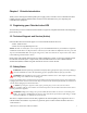
Chapter 10 Active Tower and Rackmount Specifications Table 5. Chloride Active UPS North America UPS Model Active 700 Active 1000 Active 2000 Active 3000 700 VA 1 kVA 2 kVA 3 kVA Electrical Data Rating Input Voltage 120 VAC single-phase Voltage range A 80 - 138 VAC Frequency 50/60Hz ± 0.5% Power factor (lambda) >0.95 Battery Integrated battery type Lead-calcium, maintenance-free Battery voltage (V) 24 36 96 96 Runtimes (min.
Table 5.
Table 5. Chloride Active UPS North America UPS Model Active 700 Active 1000 Active 2000 Active 3000 5-15P 5-15P L5-20P L5-30P 10 A 15 A 20 A 30 A 3 3 3/1 3/1 Type 5-15R 5-15R 5-15R/L520R 5-15R/L530R Maximum current (at 120 VAC, pf = 0.7) 5.8 A 8.3 A 16.
Table 6. Active Rackmount Technical Data for North American Models Type Active700-19 Active1000-19 Active2000-19 Active3000-19 19 x 3.5 x 17.6 19 x 3.5 x 17.6 19 x 3.5 x 18.8 19 x 3.5 x 18.8 16.1 x 3.5 x 16.1 16.1 x 3.5 x 16.1 16.1 x 3.5 x 17.3 16.1 x 3.5 x 17.3 33 (15) 40 (18) 27 (12) 30 (13.5) Dimensions Unit dimensions - WxHxD - in. (mm) Body dimensions - WxHxD in.
10.1 Battery Lifetime 10 1 0,1 10 50 20 68 30 86 40 104 50 C 122 F Ambient Temperature Fig. 19: Typical lifetime of the batteries Figure 19 shows the typical lifetime of the batteries which are used in the UPS devices, depending on the devices’ ambient temperature.
Chapter 11 Chloride Introduction Thank you for selecting this uninterruptible power supply (UPS). Chloride’s E-Series UPS offer the most reliable protection from the harmful effects of electrical line disturbances for your computing and communications equipment. 11.1 Registering your Chloride E-Series UPS To ensure that your E-Series model and serial number are registered, complete and mail the enclosed postage-paid warranty card. 11.
the equipment in service it must be absolutely dry. An acclimatization period of at least two hours is required. • This equipment must be installed in an indoor, temperature controlled environment that is free of conductive contaminants. See chapter 19, “E-Series Specifications” on page 50 for specific environmental limits. • The special conditions for installing the hard-wired devices E61, E101 and E203 in chapter 13, “ESeries Installation and Commissioning” on page 33 must be observed.
Chapter 12 Display and Operation Elements (E-Series) The Uninterruptible Power System (UPS) is connected between AC power and the load. It protects the load against mains disturbances, especially power failures. Its operation is based on the on-line principle. The connected load is supplied power through the UPS’s inverter. Power disturbances from the mains are suppressed which increases the loads’ operational security (PC, network server, multi-user systems etc.
This operation manual contains all relevant information to install and operate the UPS. 12.1 Front The OVERLOAD indicator is on when the UPS is overloaded. The LED-chain LOAD indicates the load state of the UPS. The BYPASS indicator is on when the UPS supplies a voltage via the bypass. The INVERTER indicator is on when the inverter is in operation. The LED-chain BATTERY indicates the battery’s charge state (normal operation) or the % of battery time remaining when mains fail.
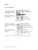
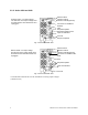
12.2 Rear 12.2.1 E-Series E61 and E101 Selector switch Interface COM A Interface COM B (optional) Selector switch - for output voltage The selection of the output voltage must be made with the UPS switched off.* Fans Output circuit breaker External battery connector (E61 with optional PDU shown) Input circuit breaker Optional PDU Fig.
Selector switch Interface COM A Interface COM B (optional) Selector switch - for output voltage The selection of the output voltage must be made with the UPS switched off.* Fans (E101 with optional PDU shown) Output circuit breaker Input circuit breaker Mains fuse and Battery switch Optional PDU Fig. 21: E81 or E101 * Call Chloride Technical Services for information on setting output voltages ((800) 388-4234 or (847) 990-3228) 12.2.
Chapter 13 E-Series Installation and Commissioning Upon receipt of your UPS, carefully examine the packing containers for any sign of physical damage. Notify the carrier immediately if damage is present. Carefully unpack the UPS. Retain the packaging for reuse or dispose. Check the packing for damages. NOTE: If damages are detected, please inform the shipping agent immediately. UPS includes: • UPS device • A recharging cable is connected to external battery cabinets BPE61. 13.
manner until all GND terminals, (-) terminals and (+) terminals are connected together. See Table 10, “Minimum Requirements for E-Series UPS Installation,” on page 40 for minimum wire gage, wire temperature and screw torque requirements. For models E101 and E203, first remove the connection plate from the rear of the battery cabinet. Next, connect the wires from GND terminal on the UPS to GND wire on the battery cabinet, and then from (-) terminal on the UPS to the (-) terminal on the battery cabinet.
Table 7. Minimum Requirements for E-Series UPS Installation E61 (E41) Term ID Description E101 (E81) E203 (E153) Min. Wire Gaug e (awg) Term Torqu e (inlbs) Min. Wire Temp . (°C)* Min. Wire Gaug e (awg) Term Torqu e (inlbs) Min. Wire Temp . (°C)* Min. Wire Gaug e (awg) Term Torqu e (inlbs) Min. Wire Temp .
X1 GND L1/N L2 120 X2 X3 X4 0 88B 120 GND 208 120 LINE OUT- + 120 - GND BAT- Fig. 24: Wiring Diagram for the E101 NOTE: 120 A or 120B must be limited to 1/2 nameplate rated current. It is user’s responsibility to fuse or breaker these outputs. Fig. 25: Wiring Diagram for the E153 and E203 Fig. 26: E203 Power System NOTE: 120 A (X1-X2) or 120B (x2-x4) must be limited to 1/2 nameplate rated current. It is user’s responsibility to fuse or breaker these outputs.
13.2 Commissioning of the E-Series When connected to the mains, the batteries automatically begin charging. The UPS may be used immediately, however, full run time will not be available until the batteries are fully charged. 1. Before using the device, charge the batteries for 8 hours. 2. After charging, connect the loads to the UPS. NOTE: Do not connect any devices that overload the UPS or draw DC current from the UPS (e.g. hair dryers, vacuum cleaners). 3.
dryers, vacuum cleaners). 5. If a signal interface cable is used, connect the cable (accessory) between the UPS and the computer system. Please observe further instructions in the documentation for the accessory. 6. Switch on the loads. 7. Switch on the UPS by operating the switch | at the front plate. NOTE: If unit will not switch on, confirm that the batteries are properly connected to the unit and any battery breakers are “ON.
13.4 Commissioning of an External Battery Cabinet The following table shows the designations of the battery cabinets which are available for the UPS devices. Table 8. External Battery Packs Model Cabinet Batteries E61 (E41) BPE61 2x (20 x 7. 2 Ah) E101 (E81)/ E203 (E153) BPE101 1x (20 x 38 Ah) Disconnect the UPS from the mains and the loads from the UPS. CAUTION: Make sure that the circuit breaker on the external battery cabinet is in the OFF position.
Hardwire Fig. 28: Connection of an External Battery Cabinet to Type E101 Fig. 29: Connection of an External Battery cabinet to Type E203 WARNING: The connection of the external battery cabinet may only be done by qualified personnel in accordance with the applicable safety regulations. CAUTION: For the electrical installation, the maximum load capacity of the connection cable has to be taken into account. Table 9.
Chapter 14 Operational Characteristics (E-Series) 14.1 Ready for Operation Check To check the emergency supply feature of the UPS, it must be disconnected from the mains. When correctly functioning with charged batteries, an acoustical signal in intervals of 4 seconds will be heard. The LED “LINE” (line voltage) indicator disappears. When the interval between the acoustical signals is reduced to 1 second, the UPS will supply energy for a maximum of 3 more minutes before it is automatically switched off.
14.3 Modes of Operation There are three modes of operation, when the UPS is switched on. 14.3.1 Normal Operation, Inverter On (Mains Available) Lights Illuminated Fig. 30: Front Display Panel During Normal Operations (Mains Available) The loads are supplied through the inverter, the energy is taken from the mains. 14.3.2 Battery Operation, Inverter On (Mains Failure) Lights Illuminated During Power Failure Fig.
14.3.3 Bypass Operation, Inverter OFF (Overload > 140%) Lights Illuminated in BYPASS Operation Fig. 32: Front Display Panel During Bypass Operation (Overload > 140%) In the event of large overload (> 140%) switch-over to bypass is initiated and the inverter is blocked. The energy is taken from the mains. This is not a normal operating status. In the event of mains failure the loads will no longer be supplied (no UPS operation).
Chapter 15 Description of the Interface (E-Series) The E-Series UPS has a standard interface COM A and an optional interface COM B. Protocol data transfer signal exchange is through COM A RS232 interface or the optional interface (COM B). These interfaces can be used for: • Direct communication between UPS and a computer. • Integration of the UPS as client into a network with centralized monitoring. • Transfer of operational states to external alarm systems.
Table 10. Interface COM A Pin Number Condition SGN at pin 5 This connection point serves as a reference for all signals. RXD at pin 2 and TXD at pin 3 In conforms standard RS232 configuration. INV SHUTDOWN at pin 2 This input (pin 2: High signal +5V...+12V, > 1 second, pin 5: 0V) enables the control processor to switch off the UPS in the event of a mains failure. After the mains has been reestablished, the UPS starts again independent of this signal status.
Troubleshooting Optional Interface COM INV SHUTDOWN This input (pin 3) is enabled with a high signal (+5 V to +12 V with respect to pin 4 (0 V)) and when enabled, switches off the UPS after a mains failure has occurred. After the mains has been reestablished, the UPS starts again independent of this signal status. This input must be high for one (1) second before shut off will occur.
Chapter 16 Maintenance (E-Series) The UPS does not require maintenance by the user. When the battery expires, the UPS or the battery must be replaced by qualified electrical personnel. The typical battery’s lifetime is 4 years at an ambient temperature of 25 °C. This may vary greatly depending upon load conditions, number of outages, and environmental factors.
Chapter 17 Troubleshooting (E-Series) If a problem occurs in spite of the high reliability of the device, please review the following checks before calling Chloride Technical Services.
Chapter 18 Technical Support for your E-Series UPS 18.1 Chloride Technical Support Chloride offers 24-hour technical support. To contact Chloride Technical Services: • Phone: (800) 388-4234 or (847) 990-3229 • email: usa.service@chloridepower.com. Please check with Chloride Technical Services before attempting to repair or return any Chloride product.
Chapter 19 E-Series Specifications Table 12. Chloride E-Series UPS North America UPS Model E61XA (E41XA*) E101XA (E81*) E203XA (E153XA*) 6 kVA 10 kVA 20 kVA * Models may be upgraded to base kVA of UPS shown. Electrical Data Rating Input Voltage Voltage range 208 VAC single-phase 170 V to 276 V 176 to 276 V Frequency 208/120 threephase 177 to 240 V 50/60Hz ± 5% Power factor (lambda) >0.97 >0.
Table 12.
Table 12.
19.1 Battery Lifetime 10 1 0,1 10 50 20 68 30 86 40 104 50 C 122 F Ambient Temperature Fig. 35: Typical lifetime of the batteries Figure 19 shows the typical lifetime of the batteries which are used in the UPS devices, depending on the devices’ ambient temperature. 19.2 Optional Power Distribution Units (PDU) available 4 -10 kVA. SPDU-2-0 SPDU-0-2 SPDU-1-0 SPDU-2-8 SPDU-2-4 SPDU-3-4 Fig.
Chloride Power Protection 28430 N Ballard Drive Lake Forest, IL 60045 United States Toll Free: (800) 239-2257 Tel: (847) 990-3228 Fax: (800) 833-6829 Visit our website at www.chlorideups.com © 2003, UP Systems, Inc. All other trademarks, product and corporatate names are all property of their respected owners. Specifications contained in this document are subject to change without notice. UPLIT039 Rev.