
User's Manual


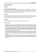

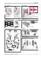
Table Of Contents
- RAy2 Microwave Link
- Table of Contents
- Important Notice
- Quick guide
- List of documentation
- 1. RAy2 – Microwave Link
- 2. Implementation Notes
- 3. Product
- 4. Accessories
- 5. Step-by-step Guide
- 6. Installation
- 7. Configuration
- 8. Command Line Interface
- 9. Troubleshooting
- 10. Technical parameters
- 11. Safety, environment, licensing
- Appendix A. Antenna dimensions
- Appendix B. Rain zone map
- Appendix C. IP address in the PC (Windows XP)
- Appendix D. IP address in the PC (Windows 7)
- Appendix E. IP address in the PC (Windows 8)
- Appendix F. SSH key generation
- Appendix G. Https certificate
- Appendix H. Unit block diagrams
- Index
- Appendix I. Revision History

6. Unit installation
Check the correct O – ring placement
on the antenna
Ensure the antenna and unit are carefully aligned
Do not use excessive force!
5. Unit polarization
Horizontal
Vertical
- the same polarization
for both units
RAy2-10, RAy2-11
RAy2-17, RAy2-24
- cross polarization
- one side – horizontal
- the other side – vertical
8. Power - PoE
Power supply
RJ45
7. Power - DC
DC cable
GND
+
+
+
+
DC
DC
DC
+
+
+
RAy2
RAy2
RAy2
GND
GND
GND
10. Sealing
Bushing
Plug
Seal unit interfaces with bushings and plugs
9. Power grounding and connections
AC 230 V
AC 230 V
PoE
PoE + Eth
DC
SWITCH
DC fibre
Units must be grounded
For surge protection - see user manual
11. Antenna alignment
Hint: Set QPSK, CS 7 MHz, max. TX power
Best RSS = minimum voltage in range 0–2 V
1
3
2
4
Step-by-step alignment – see user manual
ver. 1.7
9© RACOM s.r.o. – RAy2 Microwave Link
Quick guide