Installation and Operation Manual AMC-101 Universal Media Converter/Repeater
AMC-101 Universal Media Converter/Repeater Installation and Operation Manual Notice This manual contains information that is proprietary to RAD Data Communications Ltd. ("RAD"). No part of this publication may be reproduced in any form whatsoever without prior written approval by RAD Data Communications.
Limited Warranty RAD warrants to DISTRIBUTOR that the hardware in the AMC-101 to be delivered hereunder shall be free of defects in material and workmanship under normal use and service for a period of twelve (12) months following the date of shipment to DISTRIBUTOR.
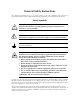
General Safety Instructions The following instructions serve as a general guide for the safe installation and operation of telecommunications products. Additional instructions, if applicable, are included inside the manual. Safety Symbols Warning This symbol may appear on the equipment or in the text. It indicates potential safety hazards regarding product operation or maintenance to operator or service personnel.
Handling Energized Products General Safety Practices Do not touch or tamper with the power supply when the power cord is connected. Line voltages may be present inside certain products even when the power switch (if installed) is in the OFF position or a fuse is blown. For DC-powered products, although the voltages levels are usually not hazardous, energy hazards may still exist.
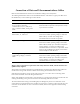
Connection of Data and Telecommunications Cables Data and telecommunication interfaces are classified according to their safety status. The following table lists the status of several standard interfaces. If the status of a given port differs from the standard one, a notice will be given in the manual. Ports Safety Status V.11, V.28, V.35, V.36, RS-530, X.
Caution Attention To reduce the risk of fire, use only No. 26 AWG or larger telecommunication line cords. Pour réduire les risques s’incendie, utiliser seulement des conducteurs de télécommunications 26 AWG ou de section supérieure. Some ports are suitable for connection to intra-building or non-exposed wiring or cabling only. In such cases, a notice will be given in the installation instructions. Do not attempt to tamper with any carrier-provided equipment or connection hardware.
Canadian Emission Requirements This Class A digital apparatus meets all the requirements of the Canadian Interference-Causing Equipment Regulation. Cet appareil numérique de la classe A respecte toutes les exigences du Règlement sur le matériel brouilleur du Canada. Warning per EN 55022 (CISPR-22) Warning This is a class A product. In a domestic environment, this product may cause radio interference, in which case the user will be required to take adequate measures.
Declaration of Conformity Manufacturer's Name: RAD Data Communications Ltd. Manufacturer's Address: 24 Raoul Wallenberg St. Tel Aviv 69719 Israel declares that the product: Product Name: AMC-101 conforms to the following standard(s) or other normative document(s): EMC: EN 55022:1998 + A1:2000, A2:2003 Information technology equipment – Radio disturbance characteristics – Limits and methods of measurement.
Quick Start Guide Installation of AMC-101 should be carried out only by an experienced technician. If you are familiar with AMC-101, use this quick start guide to set it up for operation. Perform the installation procedures for both the local and the remote units. 1. Installing AMC-101 Instructions given below detail the settings that you have to make in order to configure AMC-101 for proper operation.
Quick Start Guide Installation and Operation Manual Installing Interface Modules The AMC-101 interface modules are hot-swappable, that means they can be replaced when the unit is ON. To install an interface module: 1. Slide the module into appropriate slot. 2. Fasten the two front panel screws to secure the module to the AMC-101 frame. Connecting the Cables To connect the fiber optic cables: 1. Remove the protective caps from the connectors and store them in a safe place for later use. 2.
Contents Chapter 1. Introduction 1.1 Overview..................................................................................................................... 1-1 Applications.......................................................................................................................... 1-1 Features................................................................................................................................ 1-1 1.2 Physical Description........................................
Table of Contents ii Installation and Operation Manual AMC-101
Chapter 1 Introduction 1.1 Overview AMC-101 is a universal modular media converter that provides retimed or transparent conversion of optical and electrical signals for ATM, SDH/SONET, FDDI, Fast Ethernet and other protocols at data rates of up to 155 Mbps. The AMC-101 modules are also available as cards for LRS-101 broadband rack, holding up to 14 cards. Applications Figure 1-1 illustrates AMC-101 in an ATM extension application.
Chapter 1 Introduction • • Installation and Operation Manual FDDI Fast Ethernet. Retimed modules provide clock regeneration and data reshaping. Transparent Media Conversion AMC-101 supports transparent conversion of fiber optic signals up to 155 Mbps for: • ATM/SDH/SONET • Ethernet • Token Ring. Transparent modules provide low-cost conversion for applications that do not require repeating or reclocking. In addition, AMC-101 provides Ethernet bridging over fiber optic links.
Installation and Operation Manual Chapter 1 Introduction Table 1-1. Fiber Optic Interface Modules Module Name Transmitter Type, Wavelength Connector Type Fiber Type [nm] Typical Optical Power Receiver Sensitivity Typical Range According to Data Rates [dBm] [dBm] [km] [miles] [km] [miles] [km] [miles] 51 Mbps 100 Mbps 155 Mbps VCSEL, 850 SC, ST, FC 62.5/125, multimode -17 -30 3 1.8 2 1.2 2 1.2 LED, 1310 SC, ST 62.5/125, multimode -18 -31 4 2.4 2 1.2 2 1.
Chapter 1 Introduction Installation and Operation Manual Table 1-2.
Installation and Operation Manual 1.2 Chapter 1 Introduction Physical Description AMC-101 is a modular standalone unit intended for the desktop or 19-inch rack installation. Figure 1-3 illustrates a 3D view of a typical AMC-101 unit. Figure 1-3. AMC-101, 3D View The front panel of the unit includes interface modules, LEDs, rate selector and loopback activation pushbutton. For a detailed description of the front panel, see Chapter 3.
Chapter 1 Introduction 1.3 Installation and Operation Manual Functional Description Figure 1-4 illustrates the AMC-101 circuit blocks in the form of the functional block diagram.
Installation and Operation Manual 1.4 Modules Controls Indicators Alarm Relay Physical Technical Specifications Types and Specifications Refer to Table 1-1, Table 1-2 and Appendix A Data Rate Up to 155 Mbps Compliance ATM Forum, ITU-T G.957, G.
Chapter 1 Introduction 1-8 Technical Specifications Installation and Operation Manual AMC-101
Chapter 2 Installation and Setup This chapter describes installation and setup procedures for the AMC-101 unit. AMC-101 is delivered completely assembled. It is designed for tabletop or 19-inch rack installation. For instructions on installation of a single unit or two units in a 19-inch rack, refer to the rack mounting kit for 19-inch racks guide that comes with the RM kit. After installing the unit, refer to Chapter 3 to assure normal operation.
Chapter 2 Installation and Setup 2.3 Installation and Operation Manual Installing AMC-101 AMC-101 is a standalone device intended for tabletop or bench installation. It is delivered completely assembled. No provision is made for bolting the unit on the tabletop. To install AMC-101: 1. Determine the required configuration of AMC-101 and set the internal jumpers and switches accordingly (see Configuring AMC-101 below). 2. Install interface modules (see Installing Interface Modules below). 3.
Installation and Operation Manual Chapter 2 Installation and Setup Alarm Relay Connector Alarm Relay Card JP2 AC Power Supply GND VCC IDLE_EN JP7 Interface Module Interface Module LEDs Card Figure 2-1. PCB Layout Table 2-1.
Chapter 2 Installation and Setup Installation and Operation Manual Connecting the Interfaces Figure 2-2 illustrates the AC-powered AMC-101 unit rear panel. ALARMS Figure 2-2. AMC-101 Rear Panel (AC Version) OTHER 155 100 51 PWR FLT WRAP RATE AMC-T SIG ST/MM AMC-T TX RX SIG 850 ST/SM TX RX 1300 Figure 2-3. AMC-101 Front Panel To connect the fiber optic cables: 1. Remove the protective caps from the connectors and store them in a safe place for later use. 2.
Installation and Operation Manual Chapter 2 Installation and Setup AC Power Connection AC power should be supplied to AMC-101 through the 1.5m (5 ft) standard power cable terminated by a standard 3-prong plug. The cable is provided with the unit. To connect AC power: 1. Connect the power cable to the power connector on the AMC-101 rear panel. 2. Connect the power cable to the mains outlet. The unit turns on automatically upon connection to the mains.
Chapter 2 Installation and Setup 2-6 Installing AMC-101 Installation and Operation Manual AMC-101
Chapter 3 Operation This chapter provides the following information for the AMC-101 unit: • • AMC-101 front-panel indicators and controls Operating procedures (turn-on, front-panel indications, performance monitoring and turn-off). Installation procedures given in Chapter 2 must be completed and checked before attempting to operate AMC-101. 3.1 Front Panel Controls and Indicators Figure 3-1 shows the AMC-101 front panel. Table 3-1 lists the AMC-101 controls and indicators.
Chapter 3 Operation 3.2 Installation and Operation Manual Operating AMC-101 Turning On AMC-101 AMC-101 is turned on as soon as power is connected. When power is connected, the PWR indicator lights up and remains lit as long as AMC-101 receives power. AMC-101 requires no operator attention once installed, with the exception of occasional monitoring of front panel indicators.
Chapter 4 Alarms and Diagnostics 4.1 Alarm Relay The rear panel of AMC-101 units includes a D-type 9-pin female connector designated ALARMS. Figure 4-1 illustrates the pinout of the AMC-101 alarm relay connector. 5 4 3 2 1 9 8 7 6 Figure 4-1.
Chapter 4 Alarms and Diagnostics 4.2 Installation and Operation Manual Diagnostic Loopbacks Two simultaneous local loopbacks check performance of the interface modules installed in AMC-101 card, and their connections to the user equipment and to the network (see Figure 4-2). AMC-101 Tx Interface Module Rx User Equipment Tx Interface Module Rx Network Figure 4-2. Diagnostic Loopbacks To activate diagnostic loopbacks: • Press the WRAP button located on the AMC-101 front panel.
Appendix A Interface Modules This appendix describes modules supported by the AMC-101 converter, providing schematics of the front panel and technical specifications. A.1 Fiber Optic Modules Typical ranges are calculated according to attenuation of 0.4 db/km for 1310 nm and 0.25 db/km for 1550 nm modules. AMC-M/MM/ST/85/T AMC-T TX RX LASER CLASS 1 SIG ST/ MM 850 Figure A-1. AMC-M/MM/ST/85/T Technical Specifications Wavelength 850 nm Connector ST Transmitter Type VCSEL Fiber Type 62.
Appendix A Interface Modules Installation and Operation Manual AMC-M/MM/SC/85/T AMC-T TX RX LASER CLASS 1 SIG SC/ MM 850 Figure A-2. AMC-M/MM/ST/85/T Technical Specifications Wavelength 850 nm Connector SC Transmitter Type VCSEL Fiber Type 62.5/125, multimode Protocols Token Ring, Ethernet Timing Mode Transparent Coding Method 4B/5B, NRZ, Manchester Optical Output -18 dBm Receiver Sensitivity -30 dBm Typical Range • 3 km (1.8 miles) for 51 Mbps • 2 km (1.
Installation and Operation Manual Appendix A Interface Modules AMC-M/MM/FC/85/T AMC-T TX RX LASER CLASS 1 SIG FC/ MM 850 Figure A-3. AMC-M/MM/ST/85/T Technical Specifications Wavelength 850 nm Connector SC Transmitter Type VCSEL Fiber Type 62.5/125, multimode Protocols Token Ring, Ethernet Timing Mode Transparent Coding Method 4B/5B, NRZ, Manchester Optical Output -18 dBm Receiver Sensitivity -30 dBm Typical Range • 3 km (1.8 miles) for 51 Mbps • 2 km (1.
Appendix A Interface Modules Installation and Operation Manual AMC-M/MM/SC/13/R AMC-R TX RX SIG SC/ MM 1300 Figure A-4. AMC-M/MM/SC/13/R Technical Specifications Wavelength 1310 nm Connector SC Transmitter Type LED Fiber Type 62.5/125, multimode Protocols TAXI, FDDI, Fast Ethernet, STS-1, STS-3c/STM-1 Timing Mode Retimed Coding Method 4B/5B, NRZ Optical Output -18 dBm Receiver Sensitivity -31 dBm Typical Range • 4 km (2.4 miles) for 51 Mbps • 2 km (1.
Installation and Operation Manual Appendix A Interface Modules AMC-M/MM/SC/13/T AMC-T TX RX SIG SC/ MM 1300 Figure A-5. AMC-M/MM/SC/13/T Technical Specifications Wavelength 1310 nm Connector SC Transmitter Type LED Fiber Type 62.5/125, multimode Protocols Any two level optical protocols up to 155 Mbps Timing Mode Transparent Coding Method 4B/5B, NRZ Optical Output -18 dBm Receiver Sensitivity -31 dBm Typical Range • 4 km (2.4 miles) for 51 Mbps • 2 km (1.
Appendix A Interface Modules Installation and Operation Manual AMC-M/MM/ST/13/R AMC-R TX RX SIG ST/ MM 1300 Figure A-6. AMC-M/MM/ST/13/R Technical Specifications Wavelength 1310 nm Connector ST Transmitter Type LED Fiber Type 62.5/125, multimode Protocols TAXI, FDDI, Fast Ethernet, STS-1, STS-3c/STM-1 Timing Mode Retimed Coding Method 4B/5B, NRZ Optical Output -18 dBm Receiver Sensitivity -31 dBm Typical Range • 4 km (2.4 miles) for 51 Mbps • 2 km (1.
Installation and Operation Manual Appendix A Interface Modules AMC-M/MM/ST/13/T AMC-T TX RX SIG ST/ MM 1300 Figure A-7. AMC-M/MM/ST/13/T Technical Specifications Wavelength 1310 nm Connector ST Transmitter Type LED Fiber Type 62.5/125, multimode Protocols Any two level optical protocols up to 155 Mbps Timing Mode Transparent Coding Method 4B/5B, NRZ Optical Output -18 dBm Receiver Sensitivity -31 dBm Typical Range • 4 km (2.4 miles) for 51 Mbps • 2 km (1.
Appendix A Interface Modules Installation and Operation Manual AMC-M/SM/SC/13L/R AMC-R TX RX LASER CLASS 1 SIG SC/ SM 1300L Figure A-8. AMC-M/SM/SC/13L/R Technical Specifications Wavelength 1310 nm Connector SC Transmitter Type Laser Fiber Type 9/125, single mode Protocols TAXI, FDDI, Fast Ethernet, STS-1, STS-3c/STM-1 Timing Mode Retimed Coding Method 4B/5B, NRZ Optical Output -12 dBm Receiver Sensitivity -31 dBm Typical Range • 40 km (25 miles) for 51 Mbps • 25 km (15.
Installation and Operation Manual Appendix A Interface Modules AMC-M/SM/SC/13L/T AMC-T TX RX LASER CLASS 1 SIG SC/ SM 1300L Figure A-9. AMC-M/SM/SC/13L/T Technical Specifications Wavelength 1310 nm Connector SC Transmitter Type Laser Fiber Type 9/125, single mode Protocols Any two level optical protocols up to 155 Mbps Timing Mode Transparent Coding Method 4B/5B, NRZ Optical Output -12 dBm Receiver Sensitivity -31 dBm Typical Range • 40 km (25 miles) for 51 Mbps • 25 km (15.
Appendix A Interface Modules Installation and Operation Manual AMC-M/SM/ST/13L/R AMC-R TX RX LASER CLASS 1 SIG ST/ SM 1300L Figure A-10. AMC-M/SM/ST/13L/R Technical Specifications Wavelength 1310 nm Connector ST Transmitter Type Laser Fiber Type 9/125, single mode Protocols TAXI, FDDI, Fast Ethernet, STS-1, STS-3c/STM-1 Timing Mode Retimed Coding Method 4B/5B, NRZ Optical Output -12 dBm Receiver Sensitivity -31 dBm Typical Range • 40 km (25 miles) for 51 Mbps • 25 km (15.
Installation and Operation Manual Appendix A Interface Modules AMC-M/SM/ST/13L/T AMC-T TX RX LASER CLASS 1 SIG ST/ SM 1300L Figure A-11. AMC-M/SM/ST/13L/T Technical Specifications Wavelength 1310 nm Connector ST Transmitter Type Laser Fiber Type 9/125, single mode Protocols Any two level optical protocols up to 155 Mbps Timing Mode Transparent Coding Method 4B/5B, NRZ Optical Output -12 dBm Receiver Sensitivity -31 dBm Typical Range • 40 km (25 miles) for 51 Mbps • 25 km (15.
Appendix A Interface Modules Installation and Operation Manual AMC-M/SM/FC/13L/R AMC-R TX RX LASER CLASS 1 SIG FC/ SM 1300L Figure A-12. AMC-M/SM/FC/13L/R Technical Specifications Wavelength 1310 nm Connector FC Transmitter Type Laser Fiber Type 9/125, single mode Protocols TAXI, FDDI, Fast Ethernet, STS-1, STS-3c/STM-1 Timing Mode Retimed Coding Method 4B/5B, NRZ Optical Output -12 dBm Receiver Sensitivity -31 dBm Typical Range • 40 km (25 miles) for 51 Mbps • 25 km (15.
Installation and Operation Manual Appendix A Interface Modules AMC-M/SM/FC/13L/T AMC-T TX RX LASER CLASS 1 SIG FC/ SM 1300L Figure A-13. AMC-M/SM/FC/13L/T Technical Specifications Wavelength 1310 nm Connector FC Transmitter Type Laser Fiber Type 9/125, single mode Protocols Any two level optical protocols up to 155 Mbps Timing Mode Transparent Coding Method 4B/5B, NRZ Optical Output -12 dBm Receiver Sensitivity -31 dBm Typical Range • 40 km (25 miles) for 51 Mbps • 25 km (15.
Appendix A Interface Modules Installation and Operation Manual AMC-M/SM/SC/13LH/R AMC-R TX RX LASER CLASS 1 SIG SC/ SM 1300LH Figure A-14.
Installation and Operation Manual Appendix A Interface Modules AMC-M/SM/SC/13LH/T AMC-T TX RX LASER CLASS 1 SIG SC/ SM 1300LH Figure A-15.
Appendix A Interface Modules Installation and Operation Manual AMC-M/SM/ST/13LH/R AMC-R TX RX LASER CLASS 1 SIG ST/ SM 1300LH Figure A-16.
Installation and Operation Manual Appendix A Interface Modules AMC-M/SM/ST/13LH/T AMC-T TX RX LASER CLASS 1 SIG ST/ SM 1300LH Figure A-17.
Appendix A Interface Modules Installation and Operation Manual AMC-M/SM/FC/13LH/R AMC-R TX RX LASER CLASS 1 SIG FC/ SM 1300LH Figure A-18.
Installation and Operation Manual Appendix A Interface Modules AMC-M/SM/FC/13LH/T AMC-T TX RX LASER CLASS 1 SIG FC/ SM 1300LH Figure A-19.
Appendix A Interface Modules Installation and Operation Manual AMC-M/SM/ST/15L/R AMC-R TX RX LASER CLASS 1 SIG ST/ SM 1550L Figure A-20. AMC-M/SM/ST/15L/R Technical Specifications Wavelength 1550 nm Connector ST Transmitter Type Laser Fiber Type 9/125, single mode Protocols TAXI, FDDI, Fast Ethernet, STS-1, STS-3c/STM-1 Timing Mode Retimed Coding Method 4B/5B, NRZ Optical Output -12 dBm Receiver Sensitivity -31 dBm Typical Range • 50 km (31 miles) • 25 km (15.
Installation and Operation Manual Appendix A Interface Modules AMC-M/SM/ST/15L/T AMC-T TX RX LASER CLASS 1 SIG ST/ SM 1550L Figure A-21. AMC-M/SM/ST/15L/T Technical Specifications Wavelength 1550 nm Connector ST Transmitter Type Laser Fiber Type 9/125, single mode Protocols Any two level optical protocols up to 155 Mbps Timing Mode Transparent Coding Method 4B/5B, NRZ Optical Output -12 dBm Receiver Sensitivity -31 dBm Typical Range • 50 km (31 miles) • 25 km (15.
Appendix A Interface Modules Installation and Operation Manual AMC-M/SM/FC/15L/R AMC-R TX RX LASER CLASS 1 SIG FC/ SM 1550L Figure A-22. AMC-M/SM/FC/15L/R Technical Specifications Wavelength 1550 nm Connector FC Transmitter Type Laser Fiber Type 9/125, single mode Protocols TAXI, FDDI, Fast Ethernet, STS-1, STS-3c/STM-1 Timing Mode Retimed Coding Method 4B/5B, NRZ Optical Output -12 dBm Receiver Sensitivity -31 dBm Typical Range • 50 km (31 miles) • 25 km (15.
Installation and Operation Manual Appendix A Interface Modules AMC-M/SM/FC/15L/T AMC-T TX RX LASER CLASS 1 SIG FC/ SM 1550L Figure A-23. AMC-M/SM/FC/15L/T Technical Specifications Wavelength 1550 nm Connector FC Transmitter Type Laser Fiber Type 9/125, single mode Protocols Any two level optical protocols up to 155 Mbps Timing Mode Transparent Coding Method 4B/5B, NRZ Optical Output -12 dBm Receiver Sensitivity -31 dBm Typical Range • 50 km (31 miles) • 25 km (15.
Appendix A Interface Modules Installation and Operation Manual AMC-M/SM/SC/15LH/R AMC-R TX SIG RX SC/ SM LASER CLASS 1 1550LH Figure A-24. AMC-M/SM/SC/15LH/R Technical Specifications Wavelength 1550 nm Connector SC Transmitter Type Laser, long haul Fiber Type 9/125, single mode Protocols TAXI, FDDI, Fast Ethernet, STS-1, STS-3c/STM-1 Timing Mode Retimed Coding Method 4B/5B, NRZ Optical Output -2 dBm Receiver Sensitivity -34 dBm Typical Range • 110 km (68 miles) • 100 km (62.
Installation and Operation Manual Appendix A Interface Modules AMC-M/SM/SC/15LH/T AMC-T TX SIG RX SC/ SM LASER CLASS 1 1550LH Figure A-25. AMC-M/SM/SC/15LH/T Technical Specifications Wavelength 1550 nm Connector SC Transmitter Type Laser, long haul Fiber Type 9/125, single mode Protocols Any two level optical protocols up to 155 Mbps Timing Mode Transparent Coding Method 4B/5B, NRZ Optical Output -2 dBm Receiver Sensitivity -34 dBm Typical Range • 110 km (68 miles) • 100 km (62.
Appendix A Interface Modules Installation and Operation Manual AMC-M/SM/ST/15LH/R AMC-R TX SIG RX ST/ SM LASER CLASS 1 1550LH Figure A-26. AMC-M/SM/ST/15LH/R Technical Specifications Wavelength 1550 nm Connector ST Transmitter Type Laser, long haul Fiber Type 9/125, single mode Protocols TAXI, FDDI, Fast Ethernet, STS-1, STS-3c/STM-1 Timing Mode Retimed Coding Method 4B/5B, NRZ Optical Output -2 dBm Receiver Sensitivity -34 dBm Typical Range • 110 km (68 miles) • 100 km (62.
Installation and Operation Manual Appendix A Interface Modules AMC-M/SM/ST/15LH/T AMC-T TX SIG RX ST/ SM LASER CLASS 1 1550LH Figure A-27. AMC-M/SM/ST/15LH/T Technical Specifications Wavelength 1550 nm Connector ST Transmitter Type Laser, long haul Fiber Type 9/125, single mode Protocols Any two level optical protocols up to 155 Mbps Timing Mode Transparent Coding Method 4B/5B, NRZ Optical Output -2 dBm Receiver Sensitivity -34 dBm Typical Range • 110 km (68 miles) • 100 km (62.
Appendix A Interface Modules Installation and Operation Manual AMC-M/SM/FC/15LH/R AMC-R TX SIG RX FC/ SM LASER CLASS 1 1550LH Figure A-28. AMC-M/SM/FC/15LH/R Technical Specifications Wavelength 1550 nm Connector FC Transmitter Type Laser, long haul Fiber Type 9/125, single mode Protocols TAXI, FDDI, Fast Ethernet, STS-1, STS-3c/STM-1 Timing Mode Retimed Coding Method 4B/5B, NRZ Optical Output -2 dBm Receiver Sensitivity -34 dBm Typical Range • 110 km (68 miles) • 100 km (62.
Installation and Operation Manual Appendix A Interface Modules AMC-M/SM/FC/15LH/T AMC-T TX SIG RX FC/ SM LASER CLASS 1 1550LH Figure A-29.
Appendix A Interface Modules Installation and Operation Manual AMC-M/SF1/SC/R AMC-R LASER CLASS 1 SIG SC/ SM LASER/ SF1 Figure A-30. AMC-M/SF1/SC/R Technical Specifications Wavelength Transmit – 1310 nm, receive – 1550 nm Connector SC Transmitter Type Laser, WDM Fiber Type 9/125, single mode Protocols TAXI, FDDI, Fast Ethernet, STS-1, STS-3c/STM-1 Timing Mode Retimed Optical Output -12 dBm Receiver Sensitivity -29 dBm Typical Range • 35 km (21.7 miles) • 25 km (15.
Installation and Operation Manual Appendix A Interface Modules AMC-M/SF1/SC/T AMC-T LASER CLASS 1 SIG SC/ SM LASER/ SF1 Figure A-31. AMC-M/SF1/SC/T Technical Specifications Wavelength Transmit – 1310 nm, receive – 1550 nm Connector SC Transmitter Type Laser, WDM Fiber Type 9/125, single mode Protocols Any two level optical protocols up to 155 Mbps Timing Mode Transparent Optical Output -12 dBm Receiver Sensitivity -29 dBm Typical Range • 35 km (21.7 miles) • 25 km (15.
Appendix A Interface Modules Installation and Operation Manual AMC-M/SF2/SC/R AMC-R LASER CLASS 1 SIG SC/ SM LASER/ SF2 Figure A-32. AMC-M/SF2/SC/R Technical Specifications Wavelength Transmit – 1550 nm, receive – 1310 nm Connector SC Transmitter Type Laser, WDM Fiber Type 9/125, single mode Protocols TAXI, FDDI, Fast Ethernet, STS-1, STS-3c/STM-1 Timing Mode Retimed Optical Output -12 dBm Receiver Sensitivity -29 dBm Typical Range • 35 km (21.7 miles) • 25 km (15.
Installation and Operation Manual Appendix A Interface Modules AMC-M/SF2/SC/T AMC-T LASER CLASS 1 SIG SC/ SM LASER/ SF2 Figure A-33. AMC-M/SF2/SC/T Technical Specifications Wavelength Transmit – 1550 nm, receive – 1310 nm Connector SC Transmitter Type Laser, WDM Fiber Type 9/125, single mode Protocols Any two level optical protocols up to 155 Mbps Timing Mode Transparent Optical Output -12 dBm Receiver Sensitivity -29 dBm Typical Range • 35 km (21.7 miles) • 25 km (15.
Appendix A Interface Modules Installation and Operation Manual AMC-M/SF3/R AMC-R LASER CLASS 1 SIG SC-APC/ SM LASER/ SF3 Figure A-34. AMC-M/SF3/R Technical Specifications A-34 Wavelength 1310 nm, transmit and receive Connector SC/APC Transmitter Type Laser, single fiber Fiber Type 9/125, single mode Protocols TAXI, FDDI, Fast Ethernet, STS-1, STS-3c/STM-1 Timing Mode Retimed Optical Output -12 dBm Receiver Sensitivity -27 dBm Typical Range 20 km (12.
Installation and Operation Manual Appendix A Interface Modules AMC-M/SF3/T AMC-T LASER CLASS 1 SIG SC-APC/ SM LASER/ SF3 Figure A-35. AMC-M/SF3/T Technical Specifications AMC-101 Wavelength 1310 nm, transmit and receive Connector SC/APC Transmitter Type Laser, single fiber Fiber Type 9/125, single mode Protocols Any two level optical protocols up to 155 Mbps Timing Mode Transparent Optical Output -12 dBm Receiver Sensitivity -27 dBm Typical Range 20 km (12.
Appendix A Interface Modules A.2 Installation and Operation Manual Electrical Modules Electrical modules of AMC-101 operate over UTP, STP and coax cables. AMC-M/UTP/155/R AMC-R SIG UTP/ 155 Figure A-36. AMC-M/UTP/155/R Technical Specifications Connector RJ-45, shielded Cable Type UTP Cat 5 Protocols STS-3c Timing Mode Retimed Coding Method NRZ Impedance 100Ω Typical Range 100m (328 ft) Table A-1.
Installation and Operation Manual Appendix A Interface Modules AMC-M/UTP/155/T AMC-T SIG UTP/ 155 Figure A-37. AMC-M/UTP/155/T Technical Specifications Connector RJ-45, shielded Cable Type UTP Cat 5 Protocols STS-3c Timing Mode Transparent Coding Method NRZ Impedance 100Ω Typical Range 50m (164 ft) Table A-2.
Appendix A Interface Modules Installation and Operation Manual AMC-M/STP/155/R AMC-R SIG STP/ 155 Figure A-38. AMC-M/UTP/155/R Technical Specifications Connector DB-9, female Cable Type STP Type 1 Protocols STS-3c Timing Mode Retimed Coding Method NRZ Impedance 150Ω Typical Range 100m (328 ft) Table A-3.
Installation and Operation Manual Appendix A Interface Modules AMC-M/STP/155/T AMC-T SIG STP/ 155 Figure A-39. AMC-M/UTP/155/T Technical Specifications Connector DB-9, female Cable Type STP Type 1 Protocols STS-3c Timing Mode Transparent Coding Method NRZ Impedance 150Ω Typical Range 50m (164 ft) Table A-4.
Appendix A Interface Modules Installation and Operation Manual AMC-M/UTP/100/R AMC-R SIG UTP/ 100 Figure A-40. AMC-M/UTP/100/R Technical Specifications Connector RJ-45, shielded Cable Type UTP Cat 5 Protocols FDDI Timing Mode Retimed Coding Method NRZ Impedance 100Ω Typical Range 100m (328 ft) Table A-5.
Installation and Operation Manual Appendix A Interface Modules AMC-M/UTP/100/T AMC-T SIG UTP/ 100 Figure A-41. AMC-M/UTP/100/T Technical Specifications Connector RJ-45, shielded Cable Type UTP Cat 5 Protocols FDDI Timing Mode Transparent Coding Method NRZ Impedance 100Ω Typical Range 50m (164 ft) Table A-6.
Appendix A Interface Modules Installation and Operation Manual AMC-M/CX/BNC/155/R AMC-R TX RX SIG CX/ BNC/ 155 Figure A-42. AMC-M/CX/BNC/155/R Technical Specifications A-42 Connector BNC, coax Cable Type Coaxial Protocols STS-3c, STM-1 Timing Mode Retimed Impedance 75Ω Range Calculation 12.
Installation and Operation Manual Appendix A Interface Modules AMC-M/CX/DIN/155/R AMC-R TX RX SIG CX/ DIN/ 155 Figure A-43. AMC-M/CX/DIN/155/R Technical Specifications AMC-101 Connector DIN 47295, 1.6/5.6 coax Cable Type Coaxial Protocols STS-3c, STM-1 Timing Mode Retimed Impedance 75Ω Range Calculation 12.
Appendix A Interface Modules Installation and Operation Manual AMC-M/10BT/B AMC-R TX LINK RX COLL 10BT Figure A-44. AMC-M/10BT/B Technical Specifications Connector RJ-45, shielded Cable Type UTP Cat 5 Protocols Ethernet (10BaseT), half or full duplex Timing Mode Retimed Operation Mode Ethernet bridge Impedance 100Ω Typical Range 100m (328 ft) Table A-7.
24 Raoul Wallenberg St., Tel Aviv 69719, Israel Tel: +972-3-6458181, Fax: +972-3-6483331, +972-3-6498250 E-mail: erika_y@rad.com, Web site: www.rad.com Customer Response Form RAD Data Communications would like your help in improving its product documentation. Please complete and return this form by mail or by fax or send us an e-mail with your comments.
Error Report Type of Error(s) ❒ Incompatibility with product or Problem(s): ❒ Difficulty in understanding text ❒ Regulatory information (Safety, Compliance, Warnings, etc.) ❒ Difficulty in finding needed information ❒ Missing information ❒ Illogical flow of information ❒ Style (spelling, grammar, references, etc.) ❒ Appearance ❒ Other _________ Please list the exact page numbers with the error(s), detail the errors you found (information missing, unclear or inadequately explained, etc.
www.rad.com INTERNATIONAL HEADQUARTERS: 24 Raoul Wallenberg Street, Tel Aviv 69719, Israel, Tel: 972-3-6458181 Fax: 972-3-6498250, 972-3-6474436, Email: market@rad.com NORTH AMERICA HEADQUARTERS: 900 Corporate Drive, Mahwah, N.J. 07430, Tel: (201) 529-1100 Toll Free: 1-800-444-7234, Fax: (201) 529-5777, Email: market@radusa.com Publication No.