ASM-20 Synchronous/Asynchronous Short Range Modem Installation and Operation Manual Notice This manual contains information that is proprietary to RAD Data Communications. No part of this publication may be reproduced in any form whatsoever without prior written approval by RAD Data Communications. No representation or warranties for fitness for any purpose other than what is specifically mentioned in this manual is made either by RAD Data Communications or its agents.
Warranty This RAD product is warranted against defects in material and workmanship for a period of one year from date of shipment. During the warranty period, RAD will, at its option, either repair or replace products which prove to be defective. For warranty service or repair, this product must be returned to a service facility designated by RAD. Buyer shall prepay shipping charges to RAD and RAD shall pay shipping charges to return the product to Buyer.
Safety Warnings The exclamation point within a triangle is intended to warn the operator or service personnel of operation and maintenance factors relating to the product and its operating environment which could pose a safety hazard. Always observe standard safety precautions during installation, operation and maintenance of this product. Only a qualified and authorized service personnel should carry out adjustment, maintenance or repairs to this instrument.
Regulatory Information FCC-15 User Information This equipment has been tested and found to comply with the limits of the Class A digital device, pursuant to Part 15 of the FCC rules. These limits are designed to provide reasonable protection against harmful interference when the equipment is operated in a commercial environment.
Declaration of Conformity Manufacturer’s Name: RAD Data Communications Ltd. Manufacturer’s Address: 12 Hanechoshet St. Tel Aviv 69710 Israel declares that the product: Product Name: ASM-20 Conforms to the following standard(s) or other normative document(s): EMC: Safety: EN 55022 (1994) Limits and methods of measurement of radio disturbance characteristics of information technology equipment.
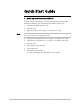
Quick-Start Guide 1. Installing and Operating ASM-20 If you are familiar with ASM-20, use this guide to prepare it for operation. Perform the following steps for both the local and the remote units. Note 20/4/99 11:47 1. Disconnect all cables from the units. 2. Open the units. 3. Adjust the jumpers. See Chapter 2, Installation and Setup. Make sure that there is only one clock source in the application: one modem INT or EXT and the other modem RCV (LBT). 4. Configure the DTE parameters.
Preface Foreword This manual provides information on the technical characteristics, installation and operating instructions of ASM-20. The manual contains the following information: Chapter 1. Introduction describes ASM-20 and its applications, features, options, physical and functional descriptions and technical specifications. Chapter 2.
Conventions Note Caution Warning A note draws attention to a general rule for a procedure, or to exceptions to a rule. A caution warns of possible damage to the equipment if a procedure is not followed correctly. A warning alerts to the presence of important operating and maintenance (servicing) instructions in the literature accompanying the equipment. If these instructions are not followed exactly, possible bodily injury may occur.
Contents CHAPTER 1 INTRODUCTION 1.1 Overview ....................................................................................................................... 1-1 Applications ..........................................................................................................................1-1 Features ................................................................................................................................1-2 Options .......................................................
Contents 3.2 Controls and Indicators................................................................................................... 3 -1 3.3 Operating Instructions .................................................................................................... 3-3 Power On Procedure ............................................................................................................3-3 Activation of Tests .......................................................................................
List of Figures Figure 1-1 Figure 1-2 Figure 1-3 Figure 1-4 Figure 1-5 Figure 1-6 Point-to-point Application ........................................................................................... 1-1 G.703 Modem Link Application .................................................................................. 1-2 Tail-end for Digital Network Application...................................................................... 1-2 ASM-20, General View.......................................................
List of Tables Table 1-1 Approximate Range....................................................................................................... 1-9 Table 2-1 ASM-20 Strap Selection Settings .................................................................................... 2-5 Table 2-2 Async Character Length Setting ..................................................................................... 2-6 Table 3-1 Control and Indicator Functions ..........................................................
Chapter 1 Introduction 1.1 Overview The ASM-20 Short Range Modem operates synchronously or asynchronously at full or half duplex, over unconditioned lines. ASM-20 has a range of up to 23 km (14 miles) and operates at selectable data rates from 19.2 kbps to 256 kbps. ASM-20 uses conditioned diphase modulation (EUROCOM Std. D1) to provide immunity from background noise, eliminate normal line distortion and enable efficient transmission and reception of serial data over a twisted pair cable.
ASM-20 Installation and Operation Manual Chapter 1. Introduction RAD A S M -2 0 R C V C LK G .7 03 D IG ITA L S E R V IC E NETW ORK RAD D TE RAD A S M -2 0 EXT CLK A S M -2 0 EXT CLK RAD A S M -2 0 R C V C LK Term ina l Figure 1-2 G.703 Modem Link Application RAD RAD A S M -2 0 A S M -2 0 G .7 03 o r X .21 /R S -5 30 /V.24 o r V.3 5 or E TH D TE Figure 1-3 Tail-end for Digital Network Application Features ASM-20 features V.
ASM-20 Installation and Operation Manual Chapter 1. Introduction Connection to an RS-449/V.36 interface is accomplished via the RS-530 interface (see Appendix A, Ethernet Interface). ASM-20 incorporates a built-in Bit Error Rate Tester (BERT). The internal BERT allows complete testing of both modems and the line without external test equipment. A front panel switch generates a pseudo-random test pattern (511-bit, according to ITU/V.52) for testing end-to-end connectivity.
ASM-20 Installation and Operation Manual 100 -11 5 VAC -0.2A T 2 50V Chapter 1. Introduction DTE XM T ~230 V/ RCV GND 0.1A T 250V Figure 1-5 ASM-20 Rear Panel with V.35 Interface 1.3 Functional Description This section contains functional descriptions of the circuit blocks in ASM-20, primarily those circuits which are required for configuring the modem (see Figure 1-6).
ASM-20 Installation and Operation Manual Modulation Timing Chapter 1. Introduction This circuit supplies the transmit clock to the encoder. Three clock sources are available: • Internal oscillator • External from the DTE • Loop clock derived from the receive signal. Setting the XMT CLK jumper determines the timing option. See Setting Internal Jumpers and Switches in Chapter 2 for more information. XMT Level (optional) Two options are available for the XMT level (signal level): 0 and -6 dBm.
ASM-20 Installation and Operation Manual Chapter 1. Introduction characters. The remote converter will add a shorter stop bit (shorter by 12.5% or 25%) before sending the data to the remote DTE. A suitable operation of the ASYNC to SYNC converter is selected by adjusting the proper character length and frequency deviation setting (dip switch bank), see Figure 2-3 and Table 2-2. X.21 Buffer (for X.21 interface) To allow tail-end connection on an X-21 interface, a buffer is provided on received data.
ASM-20 Installation and Operation Manual Digital Interface Type Chapter 1. Introduction • V.24/RS-232 via 25-pin D-type, (up to 64 kbps only), female connector • V.35 via 34-pin female connector • X.21 via 15-pin D-type female connector • RS-530 (RS-422) via 25-pin D-type female connector • V.36 (RS-449) via 37-pin female connector using mechanical cable adapter provided with the product • G.
ASM-20 Installation and Operation Manual Chapter 1. Introduction Power PWR (green) Request to Send RTS (yellow) Transmit Data TD (yellow) Receive Data RD (yellow) Data Carrier Detect DCD (yellow) Test TEST (red) Bit errors Err Electrical Power Supply 115 or 230 V (± 10%) 47 to 63 Hz; 5W -48 VDC or 24 VDC Physical ASM-20 Modem Height: Width: Depth: Weight: ASM-20-R Card Dimensions: Fits ASM-MN-214 modem rack Indicators (yellow) 44 mm 215 mm 243 mm 1.1 kg / 1.7 in / 8.5 in / 9.
ASM-20 Installation and Operation Manual Chapter 1. Introduction Table 1-1 Approximate Range Baud Rate kbps 19 AWG (0.8 mm) km miles 22 AWG (0.6 mm) km miles 24 AWG (0.5 mm) km miles 26 AWG (0.4 mm) km miles 256 3.75 2.3 2.85 1.75 2.25 1.4 1.9 1.2 192 6.0 3.7 4.5 2.8 3.5 2.2 2.7 1.7 144 10.6 6.6 6.75 4.2 4.5 2.8 3.4 2.1 128 12.4 7.7 7.3 4.5 5.0 3.1 3.6 2.2 115.2* 12.8 7.8 7.65 4.75 5.25 3.3 3.8 2.5 112 12.8 8.0 8.0 5.0 5.5 3.4 4.0 2.5 96 13.
Chapter 1.
Chapter 2 Installation and Setup 2.1 Introduction This chapter provides instructions for mechanical and electrical installation of the ASM-20 standalone model. For rack installation of the ASM-20, see Chapter 5, Card Cage Version. Section 2.2 describes site preparation for ASM-20. Section 2.3 lists the contents of the ASM-20 package. Section 2.4 describes the mechanical installation of ASM-20. Section 2.5 describes the electrical installation of ASM-20.
ASM-20 Installation and Operation Manual Chapter 2. Installation and Setup 2.3 Package Contents The ASM-20 package includes the following items: • ASM-20 • AC cord • 48 VDC plug (optional) • Adapter cable for the different interfaces (optional) • ASM-20 Installation and Operation Manual. 2.4 Mechanical Installation ASM-20 is a standalone device designed to be placed on a tabletop or bench. It is delivered completely assembled. No provisions are made for bolting ASM-20 to the tabletop. 2.
ASM-20 Installation and Operation Manual Chapter 2. Installation and Setup ~230 VAC -1A T 250V DTE &$87,21 )25 &217,18(' 3527(&7,21 $*$,167 5,6. 2) ),5( 5(3/$&( 21/< :,7+ 6$0( 7<3( $1' 5$7,1* 2) )86( X.21 Line Con nector Figure 2-2 ASM-20 - X.21 Rear Panel Strap Selection Before connecting power to the unit, determine the required configuration of ASM-20 and position the straps accordingly.
9 8 7 A D C B AL B DT E J8 0 - 256 1 - 192 2 - 144 3 - 128 4 - 115.2 5 - 112 6 - 96 7 - 72 8 - 64 9 - 57.6 A - 56 B - 48 C - 38.4 D - 32 E - 2 8.8 F - 19.2 6 B AU D R AT E kbps 3 4 5 1 2 0 F DIS R LB D TE EN * J7 E DIS C HAS S J12 EN LO W -6 d bm OFF J11 J9 J14 D IS 15 0 0 d bm X M T IM P X M T LVL ON H IG H HIG H R PF. R CV IM P 1 50 RC V LVL LO W J10 J13 CO N ASM-20 Installation and Operation Manual Chapter 2.
ASM-20 Installation and Operation Manual Chapter 2. Installation and Setup Table 2-1 ASM-20 Strap Selection Settings Jumper and Switch Identity Function Possible Settings Factory Setting J1 V54 DIS Prevents activation of remote V.54 loops. EN DIS EN J2 CARRIER Selects the transmit carrier mode. When ON, transmit carrier is constantly ON. When CNTRL, transmit carrier is ON only when RTS is High. In X.21, RTS is replaced by the CONTROL signal.
ASM-20 Installation and Operation Manual Chapter 2. Installation and Setup Table 2-1 ASM-20 Strap Selection Settings (Cont.) Jumper and Switch Identity Function Possible Settings SW2 ASYNC LENGTH (3 dip switches) Select character length in async mode (see Table 2-2 for further explanation). S1 S2 OFF ON OFF ON OFF OFF ON ON Factory Setting No. Bits S1 = OFF 8 9 10 11 S2 = OFF S3 = ON S3 Selects the stop bit reduction rate to be used in async mode.
ASM-20 Installation and Operation Manual Chapter 2. Installation and Setup Power Connection AC power is supplied to ASM-20 through a standard 1.5 m (5 ft) detachable power cord terminated by a standard 3-prong plug. The power inlet on the rear panel incorporates an integral fuse. Warning Before connecting AC power to this unit, the protective earth terminals of this unit must be connected to the protective ground connector of the (mains) power cord.
Chapter 2.
Chapter 3 Operation 3.1 General This chapter: • Describes the controls and indicators of ASM-20 and their functions • Explains the operation procedures • Provides jumper and switch information. Installation procedures given in Chapter 2, Installation and Setup must be completed and checked before attempting to operate the ASM-20. 3.2 Controls and Indicators All controls (push button switches) and LED indicators are located on the ASM-20 front panel.
ASM-20 Installation and Operation Manual Chapter 3. Operation PW R 1 RT S 2 TD 3 4 DCD 5 TE S T ERR 7 RPF E D IG A ANA B C PATT D A S M - 20 Figure 3-2 ASM-20R Front Panel Table 3-1 Control and Indicator Functions Item Name Type Function A DIG Pushbutton The Digital Loopback switch causes the local ASM-20 to loop received data and clock back to its transmitter. Data Set Ready will turn off (see Figure 4-5). B ANA Pushbutton The Analog Loopback (V.
ASM-20 Installation and Operation Manual Chapter 3. Operation Table 3-1 Control and Indicator Functions (Cont.) Item Name Type Function E RPF RESET Pushbutton Resets ERR/RPF LED (only available in ASM-20/R). 1 PWR LED Indicator Green LED is on when power is on. 2 RTS LED Indicator ITU 105 Yellow LED is on when terminal activates Request to Send. 3 TD LED Indicator ITU 103 Yellow LED is on when steady SPACE is being transmitted. It flickers when data is transmitted.
ASM-20 Installation and Operation Manual Chapter 3. Operation Activation of Tests In order to verify that the ASM-20 is operating correctly, use the internal BERT and analog loopback tests as described in Bit Error Rate Tester (BERT) in Chapter 4 and Local Test - Analog Loopback in Chapter 4. Operational Jumper and Switch Changes Warning If you need to reconfigure the ASM-20 for a different type of operation, the jumpers and switches must be changed to correspond to the new operating mode.
Chapter 4 Troubleshooting and Diagnostics 4.1 General This chapter contains procedures for performing system diagnostic tests for ASM-20. Use the test procedures provided in this chapter to: • Verify normal system operation • Isolate faulty equipment in the event of failure. Tests are activated by control push buttons on the ASM-20 front panel and monitored via LED indicators. For a description of the ASM-20 controls and indicators and their functions, see Chapter 3, Operation. 4.
Chapter 4. Troubleshooting and Diagnostics ASM-20 Installation and Operation Manual Table 4-1 Differences in Versions (Cont.) ASM-20 ASM-20-2 Metal box Plastic box Terminal block with screws Clip terminal block Main chip RJ008 and external BERT chip Main chip RJ016 which includes BERT chip No CE mark CE mark No asynchronous transmission Asynchronous transmission capability The above versions are compatible with each other within similar synchronous rates.
ASM-20 Installation and Operation Manual Chapter 4. Troubleshooting and Diagnostics PATT P re sse d P a tte rn G en e rato r P a tte rn Teste r XM T RCV E rro r A S M -2 0 Figure 4-1 BERT Using Loops Alternatively, the complete link can be tested when using two ASM-20 modems or an external BERT. Figure 4-2 illustrates the two options for testing a complete link: • • Press the PATT push button of the local modem and check the ERR/RPF LED. At the remote side check an external BERT.
ASM-20 Installation and Operation Manual Chapter 4. Troubleshooting and Diagnostics 4.5 Modem Self Test The modem self test verifies that ASM-20 is operating correctly. To verify that ASM-20 is operating correctly: 1. Press the ANA (Analog Loopback) push button on the front panel. Both the TEST and DCD LEDs should light up. If the DCD LED does not light up, check that the CARRIER jumper is ON or that the RTS signal is ON (high). 2. Press the PATT push button.
ASM-20 Installation and Operation Manual Chapter 4. Troubleshooting and Diagnostics To check the performance of the local modem and the local data terminal: 1. Press the ANA (Analog Loopback) push button on the front panel (see Figure 3-1). This test can also be activated via the pin on the DTE interface. See Table 2-2 for more information. The TEST LED should turn on. ASM-20 transmit output is now connected to its own receiver (see Figure 4-3). 2.
ASM-20 Installation and Operation Manual Chapter 4. Troubleshooting and Diagnostics 3. If Step 2 indicates a fault, and if the modem test described Modem Self Test on page 4-4 was positive for both the local and remote modems, the line circuits are not operating properly.
Chapter 5 Card Cage Version 5.1 General This chapter describes the ASM-20/R card version, designed for installation in the ASM-MN-214 card cage. The chapter contains the following sections: • Section 5.2 describes the ASM-MN-214 card cage • Section 5.3 describes the ASM-20/R card version • Section 5.4 describes the power supply to ASM-20/R • Section 5.5 describes how to install ASM-20/R. 5.2 ASM-MN-214 Card Cage The ASM-MN-214 card cage contains one or two power supplies and up to 14 plug-in cards.
ASM-20 Installation & Operation Manual Chapter 5. Card Cage Version Figure 5-1 ASM-MN-214 Rear Panel 5.3 ASM-20/R Card Version Figure 5-2 shows the ASM-20/R card front panel. The LEDs and switches of the card version are identical in their functionality to those of the standalone device. For this information, refer to Section 3.1, Controls and Indicators, in Chapter 3.
ASM-20 Installation & Operation Manual Chapter 5. Card Cage Version PWR RTS TD RD DCD TES T ERR RPF D IG ANA REM PATT A S M - 20 Figure 5-2 ASM-20/R Front Panel 5.4 Power Supply Power is supplied to the ASM-20/R card from the ASM-MN-214 power supply via the chassis. Each ASM-20/R card has two fuses, which protect the entire system against power failure resulting from a short circuit in one card. The ASM-MN-214 card cage can accept both AC or DC power supplies.
Chapter 5. Card Cage Version Power Supply with Redundancy ASM-20 Installation & Operation Manual This special ordering option is equipped with two separate power supplies, operating together and sharing the load of the whole card cage. If either of the power supplies fails, the other one will continue to supply power to the full card cage. Two LED indicators show activity of each power supply. They should both light when mains power is provided.
ASM-20 Installation & Operation Manual Chapter 5. Card Cage Version 5.5 Installation To install the ASM-20/R card in the ASM-MN-214 card cage: 1. Install the ASM-MN-214 card cage in the 19" rack. 2. Adjust the jumpers and switches on the card as required (see Table 2-1 and Figure 2-3 in Chapter 2). 3. Insert the ASM-20/R card into one of the ASM-MN-214 slots. Push the bottom of the card into the cage to until it is fully inserted into the edge connector inside the rack.
Chapter 5.
Appendix A Ethernet Interface A.1 General This appendix: • Describes the IR-ETH for RAD modems • Describes the different IR-ETH connector options • Lists the Ethernet bridge specifications • Explains how to install and operate an Ethernet bridge. A.2 Description The IR-ETH is an interface module for RAD modems, used for converting the Ethernet (10BaseT or 10Base2) electrical levels to the modem TTL levels.
ASM-20 Installation and Operation Manual Appendix A. Ethernet Interface A.3 IR-ETH Connector Options Figure A-2 and Figure A-3 show the rear panel of ASM-20 with the IR-ETH connector options. The IR-ETH connector for the ASM-20/R card (rack mount version) is shown in Figure A-4.
ASM-20 Installation and Operation Manual Appendix A. Ethernet Interface A.4 Ethernet Bridge Specifications General LAN WAN LAN Table 10,000 addresses Filtering and Forwarding 15,000 pps Buffer 256 frames Delay 1 frame Standard Conforms to IEEE 802.3/Ethernet Data Rate 10 Mbps (20 Mbps 10BaseT FDX) Connectors 10BaseT (UTP): Shielded RJ-45 10Base2: BNC connector Protocol HDLC Data Rate According to the modem transmission rate A.
ASM-20 Installation and Operation Manual Appendix A. Ethernet Interface 4 3 2 1 Figure A-6 Ethernet Bridge Layout (BNC option) LAN Installation For 10BaseT installation, either a straight cable or a cross-cable may be required. Use a cross-cable when connecting to a port that does not implement the crossover function internally. Otherwise, use a straight cable. (Hubs usually implement the crossover function internally while NICs and other devices do not.
ASM-20 Installation and Operation Manual Appendix A.
Appendix A.
Appendix B IR-G.703 Codirectional Interface (64 kbps) B.1 Introduction This appendix: • • • Provides a general description of the IR-G.703 codirectional interface (64 kbps) Describes the EXT mode for the IR-G.703 codirectional interface (64 kbps) Describes the INT/RCV mode for the IR-G.703 codirectional interface (64 kbps). B.2 General Description The IR-G.703 is an interface module for RAD modems, converting G.703 codirectional signals to TTL levels.
Appendix B. IR-G.703 Codirectional Interface (64 kbps) ASM-20 Installation and Operation Manual Figure B-1 IR-G.703 Connector Options Note In Figure B-1, RCV refers to the input signals to the IR module; XMT refers to the output signals from the module. The IR-G.703 interface module is shown in Figure B-2. It has two operation modes which are selectable on the PCB board. The selection is made by means of the JP1 jumper located within the module as shown in Figure B-2.
ASM-20 Installation and Operation Manual Appendix B. IR-G.703 Codirectional Interface (64 kbps) This mode corresponds to the modem clock working in the EXT mode. Modem A Modem B IR -G .7 03 M o du le T X D a ta TX D a ta C lo c k R e c ov e ry C L K G .7 03 C o d ire ctio na l 6 4 k bp s n etw ork C lo c k Out RX F IF O C lo c k R e c ov e ry D a ta C lo c k R e c ov e ry R X D a ta Tim in g S ou rce F IF O RX TX C lo c k In E X T C loc k M od e R C V C loc k M od e Figure B-3 IR-G.
Appendix B. IR-G.
Appendix C IR-X.21B Interface Module C.1 General This appendix: • Provides a general description of the IR-X.21B interface module • Describes the IR-X.21B connectors and pin assignments • Describes the IR-X.21B interface module • Describes the EXT mode for the IR-X.21B • Describes the INT/RCV mode for the IR-X.21B. C.2 General Description The IR-X.21B is an interface module for RAD modems, converting X.21 signals to TTL levels.
ASM-20 Installation and Operation Manual Appendix C. IR- X.21B Interface Module C.3 IR-X.21B Connectors Figure C-2 shows the rear panel of a standalone ASM-20 with the IR-X.21B interface module. DTE &$ 87 , 21 )25 &217,18(' 3527(&7,21 $*$,167 5,6. 2) ),5( 5(3/$&( 21/< :,7+ 6$0( 7<3( $1' 5$7,1* 2) )86( X2 1 Line Con nector Figure C-2 ASM-20 Rear Panel with X.21 Connector The ASM-20 modem rack version requires an additional adapter to connect between the DB-15 connector of the X.
ASM-20 Installation and Operation Manual Appendix C. IR- X.21B Interface Module C.4 IR-X.21B Interface Module The IR-X.21B interface module is shown in Figure C-3. It has two operation modes which are selectable on the PCB board. The selection is made by means of the JP2 jumper located within the module as shown in the figure. The EXT mode is described in EXT Mode on page C-3 and illustrated in Figure C-4. The INT/RCV mode is described in INT/RCV Mode on page C-4 and illustrated in Figure C-5. The X.
ASM-20 Installation and Operation Manual Appendix C. IR- X.21B Interface Module MODEM (EXT) IR-X.21 Transmit Data from DTE TD (Jumpers 2,9) External Timing from DTE TC (Jumpers 6,13) RD Receive Data to DTE FIFO Buffer RC (Jumpers 4,11) DB Connector Figure C-4 EXT Mode Timing Block C.6 INT/RCV Mode This mode is used in applications where the IR-X.21B side uses the clock signal from the modem link. This mode is used mainly when the attached equipment has an IR-X.
Appendix D DTE Interface Connectors D.1. General Table D-1 provides detailed information about each DTE interface connector. Table D-1 Interface Signal List (Female Connectors) Pins and Standard Signal Names RS-232 Signal Function DB-25 Standalone and Frame V.
ASM-20 Installation & Operation Manual Appendix D. DTE Interface Connectors Table D-1 Interface Signal List (Female Connectors) Pins and Standard Signal Names (Cont.) RS-232 Signal Function DB-25 Standalone and Frame V.35 DB-25 Frame EIA-530 34-pin Standalone DB-25 Standalone and Frame Pin Circuit Pin Circuit X.
ASM-20 Installation & Operation Manual Appendix D. DTE Interface Connectors Table D-1 Interface Signal List (Female Connectors) Pins and Standard Signal Names (Cont.) RS-232 V.35 EIA-530 X.
ASM-20 Installation & Operation Manual Appendix D. DTE Interface Connectors Table D-1 Interface Signal List (Female Connectors) Pins and Standard Signal Names (Cont.) Signal Function Test Indicator D-4 RS-232 V.35 DB-25 Standalone and Frame DB-25 Frame 25 25 General EIA-530 X.
Appendix E Connection to RS-422 E.1 General Table E-1 provides detailed information for connecting an ASM-20 (EIA 530) to a RS-422 (V.36) DTE. Table E-1 Interface List for Connecting ASM-20 (RS- 530) to RS-422 (V.
ASM-20 Installation and Operation Manual Appendix E. Connection to RS-422 Table E-1 Interface List for Connecting ASM-20 (EIA 530) to RS-422 (V.36) DTE (Cont.
Appendix F Unit Case Assembly F.1 General This appendix: • Describes the unit case • Describes how to install the unit case into a 19” rack. F.2 Unit Case The unit case design facilitates quick access to the interior strappings as well as easy installation into a 19" rack. F.3 Installation of the Unit Case into a 19" Rack The height of the unit is 1U (1.75"); the width of the unit is slightly less than half the available mounting width.
ASM-20 Installation and Operation Manual Appendix F. Unit Case Assembly S h ort B ra cke t Fa sten in g S cre w s L on g B racket Figure F-1 Installation of a Single Unit Installation of Two Units F-2 Rack adapter components for installing two units include two long side rails (one for each unit) which slide one into the other fastening the two units together, and two short side brackets which hold the two units in the 19" rack. See Figure F-2.
ASM-20 Installation and Operation Manual Appendix F. Unit Case Assembly L eft-H an d U n it R a il S h ort B ra cke t R ig h t-H a nd U n it R a il S h ort B ra cke t Figure F-2 Rack Adapter Components for Installation of Two Units To install two units: 11/4/99 12:26 1. Fasten one long side rail to each unit (right side to one unit, left side to the other unit) using the four screws and flatwashers supplied.
ASM-20 Installation and Operation Manual Appendix F. Unit Case Assembly 4. Secure the supplied plastic caps to the ends of the rails, to prevent the units moving and to protect the rail ends. 5. Place the assembled units in the rack and fasten the brackets to the side rails of the rack, by means of the four screws situated on each side (not included in the kit).