INSTALLATION AND OPERATION MANUAL ASM-MN-214 Chassis for Short Range Modems The Access Company
ASM-MN-214 Chassis for Short Range Modems Installation and Operation Manual Notice This manual contains information that is proprietary to RAD Data Communications Ltd. ("RAD"). No part of this publication may be reproduced in any form whatsoever without prior written approval by RAD Data Communications.
Limited Warranty RAD warrants to DISTRIBUTOR that the hardware in the ASM-MN-214 to be delivered hereunder shall be free of defects in material and workmanship under normal use and service for a period of twelve (12) months following the date of shipment to DISTRIBUTOR.
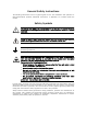
General Safety Instructions The following instructions serve as a general guide for the safe installation and operation of telecommunications products. Additional instructions, if applicable, are included inside the manual. Safety Symbols This symbol may appear on the equipment or in the text. It indicates potential safety hazards regarding product operation or maintenance to operator or service personnel.
Handling Energized Products General Safety Practices Do not touch or tamper with the power supply when the power cord is connected. Line voltages may be present inside certain products even when the power switch (if installed) is in the OFF position or a fuse is blown. For DC-powered products, although the voltages levels are usually not hazardous, energy hazards may still exist.
Before connecting the DC supply wires, ensure that power is removed from the DC circuit. Locate the circuit breaker of the panel board that services the equipment and switch it to the OFF position. When connecting the DC supply wires, first connect the ground wire to the corresponding terminal, then the positive pole and last the negative pole. Switch the circuit breaker back to the ON position.
there are restrictions on the diameter of wires in the telecom cables, between the equipment and the mating connectors. Caution To reduce the risk of fire, use only No. 26 AWG or larger telecommunication line cords. Attention Pour réduire les risques s’incendie, utiliser seulement des conducteurs de télécommunications 26 AWG ou de section supérieure. Some ports are suitable for connection to intra-building or non-exposed wiring or cabling only.
FCC-15 User Information This equipment has been tested and found to comply with the limits of the Class A digital device, pursuant to Part 15 of the FCC rules. These limits are designed to provide reasonable protection against harmful interference when the equipment is operated in a commercial environment.
Français Mise au rebut du produit Afin de faciliter la réutilisation, le recyclage ainsi que d'autres formes de récupération d'équipement mis au rebut dans le cadre de la protection de l'environnement, il est demandé au propriétaire de ce produit RAD de ne pas mettre ce dernier au rebut en tant que déchet municipal non trié, une fois que le produit est arrivé en fin de cycle de vie.
• Avant la mise en marche de l'équipement, assurez-vous que le câble de fibre optique est intact et qu'il est connecté au transmetteur. • Ne tentez pas d'ajuster le courant de la commande laser. • N'utilisez pas des câbles ou connecteurs de fibre optique cassés ou sans terminaison et n'observez pas directement un rayon laser. • L'usage de périphériques optiques avec l'équipement augmentera le risque pour les yeux.
Français Connexion au courant du secteur Assurez-vous que l'installation électrique est conforme à la réglementation locale. Branchez toujours la fiche de secteur à une prise murale équipée d'une borne protectrice de mise à la terre. La capacité maximale permissible en courant du circuit de distribution de la connexion alimentant le produit est de 16A.
Declaration of Conformity Manufacturer's Name: RAD Data Communications Ltd. Manufacturer's Address: 24 Raoul Wallenberg St., Tel Aviv 69719, Israel declares that the product: Product Name: ASM-MN-214 conforms to the following standard(s) or other normative document(s): EMC: Safety: EN 55022 (1994) Limits and methods of measurement of radio disturbance characteristics of information technology equipment.
Contents 1. 2. 3. 4. 5. 6. 7. Introduction .................................................................................................................. 1 Physical Description ...................................................................................................... 2 Power Supply ................................................................................................................ 2 AC Supply (100, 115 or 230 VAC) ...............................................................
Table of Contents ii Installation and Operation Manual ASM-MN-214 Ver. 1.
Installation and Operation 1. Introduction The ASM-MN-214 is a rack-mount chassis for modems, CSUs/DSUs and converters. The chassis accommodates up to 14 cards, and supports more than 20 different types of cards. Any combination of plug-in cards can be installed. Cards can be removed or inserted during operation without affecting the operation of other cards. It can be powered from either AC or DC power sources, or from both.
Quick Start Guide Installation and Operation Manual 2. Physical Description ASM-MN-214 is a 19-inch, 4U high, rack-mount chassis. A 3-D view of a typical unit is shown in Figure 2. Figure 2. ASM-MN-214 Chassis 2 Physical Description ASM-MN-214 Ver. 1.
Installation and Operation Manual 3. Quick Start Guide Power Supply The ASM-MN-214 chassis can accept both AC or DC power supplies (PS). LED indicators located on the ASM-MN-214 front panel show activity when the power supply is connected to the mains plug (see Figure 2). The power supply supports the full chassis with any combination of cards. AC Supply (100, 115 or 230 VAC) The AC power supply of the ASM-MN-214 accepts 100, 115 or 230 VAC, ±10%, 50/60 Hz.
Quick Start Guide Installation and Operation Manual 4. Line and DTE Connectors For each of the 14 cards, the rear panel (see Figure 3) contains line and DTE connectors. Line Interface Line interface of ASM-MN-214 may terminate in the following connectors: • 5-screw terminal block • BNC coaxial • RJ-45. Terminal Block Option The terminal block contains five screws for connecting the transmit and receive pairs and ground, if present.
Installation and Operation Manual Quick Start Guide BNC Coaxial Option Another version of ASM-MN-214 is the ASM-MN-214/BNC. The line interface of that option terminates in two BNC coaxial connectors. The rear panel of ASM-MN-214/BNC is illustrated in Figure 4. Figure 4. ASM-MN-214-BNC Rear Panel RJ-45 Option Another version of ASM-MN-214 is the ASM-MN-214-RJ. The line interface of that option terminates in RJ-45 connectors. The rear panel of ASM-MN-214-RJ is illustrated in Figure 5. CIA/V.35/1 CIA/X.
Quick Start Guide Installation and Operation Manual DTE Interface The 25-pin D-type female interface connector provides all interface signals for the digital interfaces. Units with an X.21 or V.35 interface require an external mechanical adapter. Two optional attachments, CIA/X21/1 and CIA/V35/1, can be ordered separately from RAD. CIA/X21/1 converts one DB-25 connector to one X.21 15-pin connector. CIA/V35/1 converts the DB-25 connector to a V.35 34-pin connector (see Figure 3).
Installation and Operation Manual 6. Quick Start Guide Plug-In Cards The plug-in card types can be any ASM-MN-214 RAD rack version modems, CSUs/DSUs or converters (any combination of up to 14 cards). Table 1 lists the available plug-in cards. Note Maximum number of plug-in cards supported by ASM-MN-214 depends on the card type and its interface. For information on possible limitations, refer to installation and operation manual of the specific card. Table 1.
Quick Start Guide Installation and Operation Manual 7. Warning Installing ASM-MN-214 GROUNDING – This unit should always be grounded through the protective earth lead of the power cable. Before connecting AC power to this unit, the mains plug should be inserted only in a socket outlet provided with a protective earth contact. The protective action must not be obstructed by use of an extension cord (power cable) without a protective conductor (grounding).
Installation and Operation Manual Note Quick Start Guide Fifth screw – to ground (optional). Modems operating over 2-wire lines use XMT terminals for the receive and transmit pairs. 4. If required, attach the appropriate CIA (CIA/X.21/1, CIA/V.35/1, CIA/ETH) or V.36 adapter cable to the DB-25 connector on the chassis rear panel. 5. Connect the DTE cable to the DB-25 connector, other side of CIA or adapter cable (depending on your version of the card interface). 6.
Quick Start Guide 10 Installing ASM-MN-214 Installation and Operation Manual ASM-MN-214 Ver. 1.
24 Raoul Wallenberg Street, Tel Aviv 69719, Israel Tel: +972-3-6458181, Fax +972-3-6483331, +972-3-6498250 E-mail: erika_y@rad.com, Web site: http://www.rad.com Customer Response Form RAD Data Communications would like your help in improving its product documentation. Please complete and return this form by mail or by fax or send us an e-mail with your comments. Thank you for your assistance! Manual Name: ASM-MN-214 Ver. 1.
Error Report Type of error(s) or problem(s): Incompatibility with product Difficulty in understanding text Regulatory information (Safety, Compliance, Warnings, etc.) Difficulty in finding needed information Missing information Illogical flow of information Style (spelling, grammar, references, etc.) Appearance Other Please list the exact page numbers with the error(s), detail the errors you found (information missing, unclear or inadequately explained, etc.
Publication No. 609-200-03/08 International Headquarters 24 Raoul Wallenberg Street Tel Aviv 69719, Israel Tel. 972-3-6458181 Fax 972-3-6498250, 6474436 E-mail market@rad.com North America Headquarters 900 Corporate Drive Mahwah, NJ 07430, USA Tel. 201-5291100 Toll free 1-800-4447234 Fax 201-5295777 E-mail market@radusa.com www.rad.