
Specifications


Quick Start Guide Installation and Operation Manual
6 Technical Specifications ASM-MN-214 Ver. 1.0
DTE Interface
The 25-pin D-type female interface connector provides all interface signals for
the digital interfaces. Units with an X.21 or V.35 interface require an external
mechanical adapter. Two optional attachments, CIA/X21/1 and CIA/V35/1, can be
ordered separately from RAD. CIA/X21/1 converts one DB-25 connector to one
X.21 15-pin connector. CIA/V35/1 converts the DB-25 connector to a V.35 34-pin
connector (see
Figure 3
).
FCD units (FCD-1L/R, FCD-2L/R and FCD-2L/R/LTU) require the following interface
adapters: CIA-FCD2L/V.35/1, CIA-FCD2L/X.21/1 and CIA-FCD2L/ETU/1.
V.36 cards are supplied with a RAD adapter cable CBL-530/449, which converts
between the DB-25 connector and a V.36 37-pin connector.
Units with Ethernet interface use a CIA/ETH interface adapter, which converts one
DB-25 connector to an RJ-45 connector.
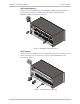
5. Technical Specifications
Number of Slots
14
Power
AC Source
100, 115 or 230 VAC (±10%), 100W, 50/60 Hz
DC Source
-48 VDC, 150W, -36 to -72 VDC
24 VDC, 150W, 18 to 32 VDC
Connectors
Line
5-screw terminal block
BNC coax
RJ-45
DTE
14 25-pin, D-type female connectors
Physical
Height
180 mm (7.0 in) (4U)
Width
48.2 mm (19.0 in)
Depth
26.7 mm (10.4 in)
Weight
ASM-MN-214: 3.6 kg (7.9 lb)
ASM-214/PS/100: 2 kg (4.4 lb)
ASM-214/PS/115: 2 kg (4.4 lb)
ASM-214/PS/230: 2 kg (4.4 lb)
ASM-214/PS/48: 0.7 kg (1.5 lb)
ASM-214/PS/24: 0.6 kg (1.3 lb)
Environment
Temperature
0°–50°C (32°–122°F)
Humidity
Up to 90%, non-condensing
Note