
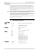
Specifications


Quick Start Guide Installation and Operation Manual
8 Installing ASM-MN-214 ASM-MN-214 Ver. 1.0
7. Installing ASM-MN-214
GROUNDING – This unit should always be grounded through the protective earth
lead of the power cable. Before connecting AC power to this unit, the mains plug
should be inserted only in a socket outlet provided with a protective earth
contact. The protective action must not be obstructed by use of an extension
cord (power cable) without a protective conductor (grounding). Interrupting the
protective (grounding) conductor (inside or outside the unit), or disconnecting
the protective earth terminal can make this unit dangerous.
Make sure that only fuses of the required rating, as marked on the
ASM-MN-214 rear panel, are used for replacement. Always disconnect the mains
cable before removing or replacing the fuse.
Site Requirements and Prerequisites
AC-powered ASM-MN-214 units should be installed within 1.5m (5 ft) of an easily
accessible grounded AC outlet capable of furnishing the voltage in accordance
with ASM-MN-214 nominal supply voltage.
DC-powered ASM-MN-214 unit requires a -48 VDC or 24 VDC power source, which
must be adequately isolated from the main supply.
Allow at least 90 cm (36 in) of frontal clearance for operating and maintenance
accessibility. Allow at least 10 cm (4 in) clearance at the rear of the unit for signal
lines and interface cables.
The ambient operating temperature of ASM-MN-214 should be 0 to 50°C (32 to
122°F), at a relative humidity of up to 90%, non-condensing.
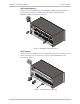
Installing a Plug-In Card into the ASM-MN-214 Chassis
³ To install the plug-in card in the ASM-MN-214 chassis:
1. Install the ASM-MN-214 chassis in the 19-inch rack.
2. Insert the plug-in card into one of the ASM-MN-214 slots.
3. Push the card into the cage until it is fully inserted into the edge connector
inside the rack.
4. Tighten the screws on front panel of the modem card.
Connecting the Interfaces
³ To connect interfaces:
1. Remove the protection cover from the terminal block connectors.
2. Connect the terminal block to the ASM-MN-214 terminal block connector.
3. Connect the line to the terminal block as follows:
Transmit pair – to the terminals marked XMT
Receive pair – to the terminals marked RCV,
Warning