
Specifications


Installation and Operation Manual Quick Start Guide
ASM-MN-214 Ver. 1.0 Installing ASM-MN-214 9
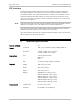
Fifth screw – to ground (optional).
Modems operating over 2-wire lines use XMT terminals for the receive and
transmit pairs.
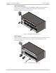
4. If required, attach the appropriate CIA (CIA/X.21/1, CIA/V.35/1, CIA/ETH) or
V.36 adapter cable to the DB-25 connector on the chassis rear panel.
5. Connect the DTE cable to the DB-25 connector, other side of CIA or adapter
cable (depending on your version of the card interface).
6. Connect power to the ASM-MN-214 chassis:
To connect AC power, connect the power cable to the mains supply.
To connect DC power, refer to the 24 VDC supplement or 48 VDC
supplement.
Note