
- RAD Data Communications Modem User's Manual


Installation
ASMi-450 Installation and Operation Manual 2-3
2.4 ASMi-450 Configuration Information
General
This paragraph provides information on the functions of the internal jumpers
and switches, to help in the selection of the correct setting for particular
application, and gives step-by-step instructions for performing the internal
settings. The default settings are also listed.
All the other configuration actions can be performed from the front panel or from
a control terminal, after the installation is completed. Information and detailed
instructions for these operations appear in Chapters 3 and 4, respectively.
Prior to ASMi-450 installation, it is necessary to check the positions of its
internal jumpers and switches. If necessary, change the settings in accordance
with the specific requirements of your application.
Warning - Electrical Shock Hazard
Access to the inside of the unit is permitted only to qualified and authorized
service personnel.
Disconnect the unit from the power line and from all the cables before
removing cover.
Line voltages are present inside the ASMi-450 when it is connected to
power and/or to the lines. Moreover, under external fault conditions
dangerous voltages may appear on the lines connected to the ASMi-450.
Any adjustment, maintenance, and repair of the opened instrument under
voltage should be avoided as much as possible and, when inevitable, should
be carried out only by a skilled technician who is aware of the hazard
involved. Capacitors inside the instrument may still be charged even after
the instrument has been disconnected form its source of supply.
Caution
The ASMi-450 contains components sensitive to electrostatic discharge (ESD).
To prevent ESD damage, avoid touching the internal components, and before
moving jumpers, touch the ASMi-450 frame.
Opening ASMi-450
Case
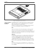
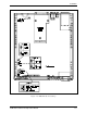
To reach the internal jumpers and switches of the ASMi-450, it is necessary to
open its case. The case cover is held by four screws, identified in figure 2-1.
After releasing the screws, the cover can be removed.
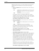
Use the following procedure:
• Disconnect all the cables connected to the ASMi-450.
• Refer to figure 2-1, turn the unit over, and unscrew the four cover screws.
Keep the screws in a safe place.
• After the four screws are released, remove ASMi-450 top cover by pulling
it straight up.