
- RAD Data Communications Modem User's Manual


ASMi-450 Control from the Control Port
4-2 ASMi-450 Installation and Operation Manual
4.2 Hardware Requirements
Terminal
Characteristics
Any standard ASCII terminal (“dumb” terminal or personal computer emulating
an ASCII terminal) equipped with an RS-232 communication interface can be
used to control ASMi-450 operation. The software necessary to run the
ASMi-450 control program is contained in the ASMi-450.
Communication
Requirements
The control terminal can be connected either directly to the ASMi-450 control
port (the CONTROL DCE connector), or through a modem or any other type of
full-duplex data link. The ASMi-450 control port interface type must be set in
accordance with the connection method (see Section 3-5):
• DCE for direct connection.
• DTE for connection through a modem or data link (cross cables must then
be used at the ASMi-450 CONTROL DCE connector).
The ASMi-450 can communicate with the control terminal at rates of 300, 1200,
2400, 4800 or 9600 bps. The word format consists of one stop bit and 7 or 8
data bits. Parity can be odd, even or disabled.
The communication interface of the terminal and the ASMi-450 must be
configured for operation with the same parameters.
The ASMi-450 supports two types of modems:
• Dial-up Hayes compatible modems, e.g., the RAD miniature DLM/AT
modem. The ASMi-450 has only a call-in capability, that is, it can accept
external calls, but cannot initiate calls.
• Multidrop modems, e.g., the RAD SRM-6 miniature multidrop modem.
For multidrop operation, each ASMi-450 can be assigned a node address in the
range of 1 through 255. Assigning address 0 to the ASMi-450 means that it will
accept and answer any message: this is not permitted in multidrop operation.
Address 0 is however recommended for use with both point-to-point and dial-up
modes.
Each ASMi-450 can be assigned a logical name of up to eight characters. The
logical name is sent in each transmission of alarm messages. The name helps the
operator to identify the source of messages that are received by the control
terminal.
The relevant ASMi-450 configuration parameters are described in Section 3-5
and 4-5. Instructions for configuring the ASMi-450 control port appear in
Section 3-7.
Handshaking
Protocol
The handshaking between the ASMi-450 and the control terminal uses the
control lines in the CONTROL DCE connector located on the rear panel of the
ASMi-450.
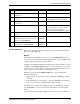
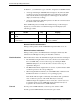
The control lines being used in each mode and the direction of the control
signals is detailed in the following chart.