
Specifications


RADring
Installation & Operation Manual Token Ring Desing Considerations
3/11/98 12:26 Token Ring Physical Design 6-5
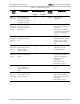
Table 6-2 UTP Cabling System
Cable
Types
Description Attenuation (dB/km) Characteristic
Impedance
@ 10 MHz
NEXT@ 10 MHz
4 Mbps 16 Mbps
IBM Type 3 Two or more
individually twisted
pair
50 100
85 - 115
Ω
23 dB
Typical EIA
RS-568
Cable
EIA standard UTP =50 100
100
Ω
30 dB
AT&T
Systimac
2061A
Super UTP cable with
special polymer
insulator
-40 82
100
Ω
44 dB
Northern
Telecom
BDN
Super UTP cable with
special polymer
insulator
-45 93
100
Ω
37 dB
Overcoming Lobe
Distance
Restrictions, and
Simplifying
Design
In designing a Token Ring Network, the maximum number of stations per
ring and the longest lobe length are major considerations in ensuring good
operation of the network.
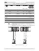
Step 1 - Lobe Media Test
The first limitation to the lobe length (distance between station and hub) is
the lobe media test. This test includes a loop test so that the signal
transmitted from the station is looped back, in order for the station to receive
and check it (see Figure 6-1). If it does not pass the test, the station cannot
enter the network. In this context, the differences between a passive lobe
and an active lobe are important, since the active lobe ensures a longer
distance at this stage of inserting into the network. The passive lobe is
transparent to the signal, so that the signal must overcome attenuation of
twice the lobe length. The active lobe regenerates the signal so that the
signal need overcome attenuation of only once the lobe length.