
Specifications


Token Ring Desing Considerations
RADring
Installation & Operation Manual
6-6 Token Ring Physical Design 3/11/98 12:26
Step 2 - Worst Case Design
Once the station is inserted, the second limitation comes into play. This
limitation is defined in terms of a worst-case situation, where the station in
question is the first station on the ring, and in addition is situated on the
longest lobe (the lobe with the highest attenuation). If passive lobes are used
and there are no repeaters on the ring, the whole drive distance around the
ring must be taken into consideration in calculating whether the drive
distance is within the attenuation limit of 26dB, the nominal budget allowed
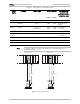
(see Figure 6-2). The worst case situation occurs when the shortest trunk
segment is broken, forcing the signal to travel along the backup path as well.
In a large ring consisting of several wiring centers these calculations can
become complicated. One way to simplify the calculations is to isolate each
wiring center in terms of network calculations. This can be done simply by
use of the repeater and jitter attenuation modules (see Section 6.5 for
standard configurations). Alternatively, once again, the active lobe modules
can be implemented to provide amplification of the signal at each lobe.
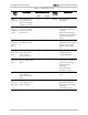
Step 3 - Selecting Active or Passive Access Lobe Modules
In the case that the lobe media test were to fail, the only solution is to use
the active lobe modules, since repeaters on the ring will not help. A table of
lobe insertion distances against cable types and data rates is given in
Table 6-3.
As can be seen from the table, even with low grade UTP, a passive lobe can
support up to 70 meters of lobe length at 16 Mbps.
In the majority of network lobes this distance is sufficient. Where possible, it
is preferable to use passive lobes rather than active lobes for two reasons:
1. Passive lobes are low cost and high density
2. Active lobes introduce added unwanted jitter, which decreases the
maximum number of stations possible or, alternatively requires jitter
attenuation. Table 6-3 displays how often a jitter attenuator should be
used for a repeater requiring it.
However, in the case that the passive lobe distances shown in the table are
not sufficient, the active lobe modules must be used providing maximum
guaranteed distances, as shown in. Table 6-3.