
Specifications

RADring
Installation & Operation Manual Functional Description
3/11/98 12:33 RI/RO Modules Functional Description 2-37
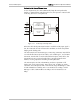
TFC/2 (Or TL-2/F) TFC/2
MAIN
REDUNDANT
REDUNDANT LINK
BECOMES ACTIVE
TX TX
TX TX
RX RX
RX RX
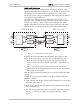
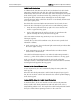
Figure 2-29 Functional Diagram of Redundant Fiber-optic
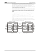
Indicators for the TFC include: Power On, Fault (ON when optical signal loss
condition exists, BLINKING when remote TFC is under optical signal loss
condition), Module configured as Ring In and Module configured as Ring
Out, and Module under network management control. LEDs will all flash
when the TFC is set to a configuration which is not allowed. The TFC is
available in two versions:
TFC/1
Single channel
TFC/2
Dual channel. The TFC/2 dual channel provides
automatic backup to the second channel in case of cable
break on the first channel.
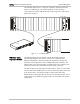
The module is available in two connector versions:
SMA Module with fiber-optic SMA connectors
(standard). Either one or two channels can be
ordered.
ST Module with fiber-optic ST connectors (optional).
Either one or two channels can be ordered.
The TFC operates in full duplex over dual fiber-optic cable for data rates of 4
or 16 Mbps. The TFC can obtain a range of 3km/1.9 miles at a wavelength of
850 nm. The optical output power for the TFC is:
•
-22 dBm into 50/125 fiber
•
-18 dBm into 62.5/125 fiber
•
-14 dBm into 100/140 fiber.
The receiver sensitivity in the TFC is minimum -32 dBm, with a dynamic range
of a minimum 20 dB. The optical power budget for three grades of fiber is:
•
10 dB for 50/125 fiber
•
14 dB for 62.5/125 fiber
•
18 dB for 100/140 fiber.
For extended distance, a special single mode version is available, providing
distances over single mode fiber of up to 29 Km.