INSTALLATION AND OPERATION MANUAL ASMi-52CQ 2-Wire Quad SHDSL Modem Card Version 2.
ASMi-52CQ 2-Wire Quad SHDSL Modem Card Version 2.12 Installation and Operation Manual Notice This manual contains information that is proprietary to RAD Data Communications Ltd. ("RAD"). No part of this publication may be reproduced in any form whatsoever without prior written approval by RAD Data Communications.
Limited Warranty RAD warrants to DISTRIBUTOR that the hardware in the ASMi-52CQ to be delivered hereunder shall be free of defects in material and workmanship under normal use and service for a period of twelve (12) months following the date of shipment to DISTRIBUTOR.
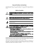
General Safety Instructions The following instructions serve as a general guide for the safe installation and operation of telecommunications products. Additional instructions, if applicable, are included inside the manual. Safety Symbols This symbol may appear on the equipment or in the text. It indicates potential safety hazards regarding product operation or maintenance to operator or service personnel.
Handling Energized Products General Safety Practices Do not touch or tamper with the power supply when the power cord is connected. Line voltages may be present inside certain products even when the power switch (if installed) is in the OFF position or a fuse is blown. For DC-powered products, although the voltages levels are usually not hazardous, energy hazards may still exist.
The maximum permissible current capability of the branch distribution circuit that supplies power to the product is 16A. The circuit breaker in the building installation should have high breaking capacity and must operate at short-circuit current exceeding 35A. Before connecting the DC supply wires, ensure that power is removed from the DC circuit. Locate the circuit breaker of the panel board that services the equipment and switch it to the OFF position.
When using shielded or coaxial cables, verify that there is a good ground connection at both ends. The earthing and bonding of the ground connections should comply with the local codes. The telecommunication wiring in the building may be damaged or present a fire hazard in case of contact between exposed external wires and the AC power lines. In order to reduce the risk, there are restrictions on the diameter of wires in the telecom cables, between the equipment and the mating connectors.
FCC-15 User Information This equipment has been tested and found to comply with the limits of the Class A digital device, pursuant to Part 15 of the FCC rules. These limits are designed to provide reasonable protection against harmful interference when the equipment is operated in a commercial environment.
Declaration of Conformity Manufacturer's Name: RAD Data Communications Ltd. Manufacturer's Address: 24 Raoul Wallenberg St., Tel Aviv 69719, Israel declares that the product: Product Name: ASMi-52CQ conforms to the following standard(s) or other normative document(s): EMC: Safety: EN 55022:1998 Information technology equipment – Radio disturbance characteristics – Limits and methods of measurement.
Quick Start Guide If you are familiar with ASMi-52CQ, use this guide to prepare the unit for operation. 1. ³ Installing ASMi-52CQ To install the ASMi-52CQ card: 1. Insert the ASMi-52CQ card into a slot of the LRS-24 chassis. 2. Insert the interface module into the upper section of LRS-24F or back of LRS-24B. 3. Connect the line and DCE cables. 2. Configuring ASMi-52CQ Accessing the Supervisory Terminal ³ To start the communication session: 1.
Quick Start Guide Installation and Operation Manual Configuring the DTE Interface To configure the ASMi-52CQ DTE interface (serial, E1 or T1), refer to the appropriate section below. Configuring the Serial Interface ³ To configure the serial interface: • In the Modem Setup menu, move the cursor to DATA RATE field by pressing and select the desired transmission rate by pressing or . Configuring the E1 Interface ³ To configure the E1 parameters: 1.
Installation and Operation Manual Unit Identical Set Receive gain Interface Transmit signal mask (DSU mode) Transmit signal mask (CSU mode) Fbit configuration. Quick Start Guide Configuring the Line Parameters ³ To configure the line parameters: 1. If you have configured E1/T1 parameters, press to return to the main menu, and then repeat the steps above to access the Modem Setup menu. 2.
Quick Start Guide 4 Configuring ASMi-52CQ Installation and Operation Manual ASMi-52CQ Ver. 2.
Contents Chapter 1. Introduction 1.1 1.2 1.3 1.4 Overview.................................................................................................................... 1-1 Product Options...................................................................................................... 1-1 Application ............................................................................................................. 1-1 Features ...........................................................................
Table of Contents Installation and Operation Manual Chapter 4. Configuration 4.1 4.2 4.3 Introduction ............................................................................................................... 4-1 Configuring the Modem .............................................................................................. 4-2 Configuring the Clock Source................................................................................... 4-2 Configuring the DTE Interface .......................
Chapter 1 Introduction 1.1 Overview ASMi-52CQ is a card containing four independent 2-wire Synchronous High Bit Rate Digital Subscriber Line (SHDSL) modems operating in full-duplex over 2-wire lines. It offers a cost effective solution delivering digital data to customer premises over existing copper cables. ASMi-52CQ handles multiples data rates in the range of 64–2304 kbps. The modem card includes four modems, supporting RS-530, V.35, X.21 and E1/T1 DTE interfaces.
Chapter 1 Introduction Installation and Operation Manual Figure 1-1. Central Site Application with SNMP Management Application Features Line Interface ASMi-52CQ operates over 2-wire lines. ASMi-52CQ extends the range of data transmission over 2-wire lines up to 7.0 km (4.3 miles), by employing SHDSL TC-PAM technology. ASMi-52CQ operation complies with the requirements of the ITU-T G.991.2 standard. Table 1-1 lists typical ASMi-52CQ ranges over 26 AWG line. Table 1-1.
Installation and Operation Manual Chapter 1 Introduction DTE Interface ASMi-52CQ supports a wide range of digital interfaces: RS-530, V.35, X.21, G.704 E1/T1, and UTP (10BaseT or 100BaseT) Ethernet interface. The required interface is provided using the appropriate interface module. Table 1-2 lists the ASMi-52CQ digital interface versions with their appropriate interface modules and DCE connectors. Note LRSI-27 (ETH) module operates with ASMi-52CQ-Ethernet card only. Table 1-2.
Chapter 1 Introduction Installation and Operation Manual Timing ASMi-52CQ supports three clock modes: • • • • Internal, derived from its internal oscillator External, supplied by the attached DTE System, supplied by the LRS-24 station clock input Receive, derived from the SHDSL line Table 1-3 details the ASMi-52CQ data rates with all possible combinations of DTE interface types and clock modes. Each port can have its own separate clocking.
Installation and Operation Manual Chapter 1 Introduction Software Download ASMi-52CQ supports downloading software from CM-2 to the local modem card. Real-time Alarms Real-time alarms provide real time information on system status indicating management failure, loss of synchronization, etc. ASMi-52CQ also features a log file that stores all alarms and events that occurred in the unit. These alarms can be displayed and cleared.
Chapter 1 Introduction Installation and Operation Manual POWER POWER DATA DATA 1 2 1 2 3 4 3 4 1 2 1 2 3 4 3 4 1 2 1 2 3 4 3 4 TST TST ALM ALM SYNC SYNC 1 2 1 2 3 4 3 4 Figure 1-2. ASMi-52CQ Front Panels The ASMi-52CQ is coupled to the LRS-24 chassis backplane and to the digital interface card by three connectors. The backplane connectors are described in Table 1-4. 1-6 Physical Description ASMi-52CQ Ver. 2.
Installation and Operation Manual Chapter 1 Introduction Table 1-4. ASMi-52CQ Connectors Connector No. of Pins Function Use J5 96 Data Carrying data and signaling to/from the Interface module in the LRS-24 chassis. J6 48 Control Carrying management information between the ASMi-52CQ module and the control module (CM-2) and supplying -5V from the chassis power supply module. J11 8 Power Supplying +5V from the chassis power supply module. 1.
Chapter 1 Introduction Installation and Operation Manual The ASMi-52CQ modem card consists of the following major modules: • SHDSL Interface Module – This module translates the received and transmitted data from the four lines to the four DTE interfaces. • Modem Glue Logic Module – This module processes the data from/to the SHDSL interface module. • Administration Data Transfer Module – This module manages the data transfer between the modems on both sides of the line.
Installation and Operation Manual Connector Chapter 1 Introduction V.35: SCSI-68 and adapter cable X.21: SCSI-68 and adapter cable RS-530: SCSI-68 and adapter cables G.704 E1: four RJ-11s (Balanced) or DB-25 female (Unbalanced) G.
Chapter 1 Introduction Environment 1-10 Installation and Operation Manual Temperature 0°–45°C (32°–113°F) Humidity Up to 90%, non–condensing Technical Specifications ASMi-52CQ Ver. 2.
Chapter 2 Installation and Operation 2.1 Introduction This chapter provides installation and operation instructions for the ASMi-52CQ card and the applicable Interface modules. The information presented in this chapter supplements the general instructions for installation and operation of the LRS-24F or LRS-24B chassis. After installing the ASMi-52CQ modem and interface module and powering up the chassis, the front panel LEDs should assume the states as shown in Chapter 3.
Chapter 2 Installation and Operation 2.3 Installation and Operation Manual Package Contents The ASMi-52CQ package includes the following items: • ASMi-52CQ modem card • Matching interface module • Technical documentation CD • Adapter cable for connecting an interface module to the appropriate DTE: RS-530 – CBL-CQ-RS530/F (if ordered) One SCSI-68 to four female RS-530 (DB-25) connectors V.35 – CBL-CQ-V35/F (if ordered) One SCSI-68 to four female V.35 (34-pin) connectors X.
Installation and Operation Manual Chapter 2 Installation and Operation Installing the Modem Card ³ To install the ASMi-52CQ card into the LRS-24 chassis: 1. Refer to the system installation plan and insert the ASMi-52CQ module in the assigned I/O slot of the LRS-24 enclosure. 2. Fasten the two front panel screws to secure the module to the LRS-24 frame for proper grounding.
Chapter 2 Installation and Operation Installation and Operation Manual Connecting the LRSI-F-18 Interface LRSI-F-18 1 2 3 L I N E 4 DCE Figure 2-2. LRSI-F-18 ³ To connect the LRSI-F-18 interface module: 1. Connect the SHDSL cables terminated in RJ-11 connectors into the card connectors marked LINE. 2. Connect a 68-pin SCSI adapter cable into the connector marked DCE. Depending on the interface, use the following cables available from RAD: Table 2-1.
Installation and Operation Manual Chapter 2 Installation and Operation Connecting the LRSI-F-19 Interface LRSI-F-19 1 L I N E 2 3 4 DCE Figure 2-3. LRSI-F-19 ³ To connect the LRSI-F-19 interface module: 1. Connect the SHDSL cables terminated in terminal blocks into the connectors marked LINE. 2. Connect a 68-pin SCSI adapter cable into the connector marked DCE. Depending on the interface, use the following cables available from RAD: Table 2-2. LRSI-F-19 Interface Adapter Cables ASMi-52CQ Ver. 2.
Chapter 2 Installation and Operation Installation and Operation Manual Connecting the LRSI-F-20 Interface LRSI-F-20 1 2 3 L I N E 4 1 2 3 D C E 4 Figure 2-4. LRSI-F-20 ³ To connect the LRSI-F-20 interface module: 1. Connect the SHDSL cables terminated in terminal blocks into the card connectors marked LINE. 2. Connect the G.704 E1/T1 balanced lines terminating in RJ-11 connectors into the card connectors marked DCE. 2-6 Connecting the Interfaces ASMi-52CQ Ver. 2.
Installation and Operation Manual Chapter 2 Installation and Operation Connecting the LRSI-F-21 Interface LRSI-F-21 1 2 3 L I N E 4 D C E Figure 2-5. LRSI-F-21 ³ To connect the LRSI-F-21 interface module: 1. Connect the SHDSL cables terminated in terminal blocks into the card connectors marked LINE. 2. Connect the G.704 E1 unbalanced lines terminating in a 25-pin D-type female connector into the card connector marked DCE.
Chapter 2 Installation and Operation Installation and Operation Manual Connecting the LRSI-F-27 Interface Figure 2-6. LRSI-F-27 ³ To connect the LRSI-F-27 interface module: 1. Connect the SHDSL cables terminated in terminal blocks into the card connectors marked LINE. 2. Connect the Ethernet lines terminating in RJ-45 connectors into the card connectors marked Ethernet. For more details on the Ethernet interface see Appendix C. 2-8 Connecting the Interfaces ASMi-52CQ Ver. 2.
Installation and Operation Manual Chapter 2 Installation and Operation Connecting the LRSI-F-28 Interface LRSI-F-28 1 L I N E 2 1 2 3 D C E 4 Figure 2-7. LRSI-F-28 ³ To connect the LRSI-F-28 interface module: 1. Connect the SHDSL cables terminated in RJ-45 connectors into the card connectors marked LINE. 2. Connect the G.704 E1/T1 balanced lines terminating in RJ-11 connectors into the card connectors marked DCE. ASMi-52CQ Ver. 2.
Chapter 2 Installation and Operation Installation and Operation Manual Connecting the LRSI-F-29 Interface LRSI-F-29 1 L I N E 2 D C E Figure 2-8. LRSI-F-29 ³ To connect the LRSI-F-29 interface module: 1. Connect the SHDSL cables terminated in RJ-45 connectors into the card connectors marked LINE. 2. Connect the G.704 E1 unbalanced lines terminating in a 25-pin D-type female connector into the card connector marked DCE.
Chapter 3 Operation This chapter: • Provides a description of the front panel controls and indicators • Explains power-on and power-off procedures • Provides instructions for using a terminal connected to the ASMi-52CQ control port • Describes how to navigate menus. 3.1 ³ Turning ASMi-52CQ On To power on ASMi-52CQ: • Turn on the LRS-24 modem rack. After power-up, all LEDs turn on for 3 seconds while the CPU initiates the ASMi-52CQ module.
Chapter 3 Operation Installation and Operation Manual POWER DATA 1 2 3 4 TST 1 2 3 4 ALM 1 2 3 4 SYNC 1 2 3 4 Figure 3-1. ASMi-52CQ Front Panel Table 3-1.
Installation and Operation Manual Chapter 3 Operation Normal Operation After power-up the LEDs should assume the states as shown in Table 3-2. Table 3-2. Normal State of LEDs 3.3 ³ ID Color State POWER Green ON DATA Yellow Blinking TST Red OFF ALM Red OFF SYNC Green/Red Green Initiating an ASCII Terminal Session To enable an ASCII terminal session: 1. Connect the terminal to the CM-2 RS-232 front connector of the LRS-24 chassis. 2. Power up the hub.
Chapter 3 Operation Installation and Operation Manual L L L L LLLL RRRRR R R RRRRR R R R RR SSSS S SS ---S SSSS 222 2 2 2 2 22222 4 4 4 4 444444 4 4 RAD DATA COMMUNICATIONS LTD Please Choose Command ID: 1. System Configuration 2. System Status 3. System manager list 4. System card type define 5. System Alarms 6. System Log-file 7. System control port 8. System Download 9. System management access 10. System Dial out modem 11. System Reset CM2 > 12. 13. 14. 15. 16. 17. 18. 19. 20. 21.
Installation and Operation Manual Chapter 3 Operation Table 3-4. Configuration Menus and Screens LRS-24 Main Menu Item Screen Name Function Modem Operation Modem Advanced Setup Setting operational parameters.
Chapter 3 Operation 3-6 Turning ASMi-52CQ Off Installation and Operation Manual ASMi-52CQ Ver. 2.
Chapter 4 Configuration This chapter describes how to configure the ASMi-52CQ modem installed in the LRS-24 hub using an ASCII terminal. It briefly describes basic modem configuration. Refer to Appendix C for a more detailed description of modem setup commands. The following items are described in this section: • Selecting menu options • Configuring the modem. 4.1 Introduction The terminal is used to configure, monitor and perform diagnostic tests of the LRS-24 chassis and modems installed in it.
Chapter 4 Configuration Installation and Operation Manual Table 4-1. LRS-24 Screens Screen Indication LRS-24 Cards Slot number in chassis where a modem is installed and type of SNMP management associated with the module, via either on-board agent (SMOD) or CM-2 agent (IMOD). ASMi-52CQ is IMOD type modem. Hub Alarm Activity status of alarms for modems installed in chassis. To view the active alarm associated with a specific modem, enter the Modem Alarms Status screen.
Installation and Operation Manual • Chapter 4 Configuration Internal – clocking comes from its internal oscillator (also known as master clocking). Figure 4-1 illustrates the various clock sources. Figure 4-1. ASMi-52CQ Clock Sources The clock source of each line in ASMi-52CQ can be configured separately with the following restrictions: ³ • External clocking cannot be used for Ethernet.
Chapter 4 Configuration Note Installation and Operation Manual • If the opposite modem is E1, then the Framed Mode value can be G732N, G732S Transparent, or Unframed. • If the opposite modem is Serial DTE or LAN, then the Framed Mode value can be G732N, or Unframed • If Frame Mode is Unframed, then all the rest of the parameters are disabled.
Installation and Operation Manual Chapter 4 Configuration Current margin, if line probing is set to adaptive Power spectral density (line probing set to fixed only) Line probing Transmission mode Loop attenuation threshold SNR margin threshold. 4.3 Memory Downloading CPU and Memory Elements Flash Memory The ASMi-52CQ flash includes the following elements: • • • • • • Boot flash memory – Contains the Boot program, essential for the modems initial operations.
Chapter 4 Configuration Installation and Operation Manual Figure 4-2. Memory Map Download Procedure The download function updates the latest software version that exists in the CM-2. The new software is stored (replacing the oldest version stored) in the Flash memory. The CM-2 modules with software version 4.0 store up to three different software release files. Previous CM-2 modules store a single software release file for ASMi-52CQ. New software releases are distributed as *.img files.
Installation and Operation Manual Chapter 4 Configuration DOWNLOAD MAIN MENU 1. Modem Download via LAN 2. Modem Download via XMODEM 3. Modem Download via CM2 FLASH 4. Modem Download via MODEM FLASH 5. Change Modem Software Version 6. View Existing Versions of Modem Enter download option number ___> Figure 4-3. Download Main Menu Downloading via LAN When this option is selected, the new software file is transferred from a server to the CM-2, using the TFTP protocol. ³ To download via LAN: 1.
Chapter 4 Configuration Installation and Operation Manual Download via XMODEM Remote modems: N/A Figure 4-5. Download via XMODEM Menu Downloading via CM-2 Flash Memory This option should be used when the CM-2 already contains a new software file that you want to download to the modem. ³ To download via CM-2 Flash memory 1. Select Modem Download via CM2 FLASH from the Modem Download menu. A menu with a list of the available software versions that reside in the CM-2 flash memory appears (see Figure 4-6).
Installation and Operation Manual Chapter 4 Configuration CHANGING MODEM’S VERSION MODEM NAME: ASMi-52CQ MODEM STATUS : MASTER PERMANENT SELECT MODEM : MODEM 1 LOCAL Modem containing the following versions: ID Version No. Date 1 0.2 2000-6-6 2 0.2E1 2001-2-22 3 0.0 0-0-0 Please choose the ID number ID NUMBER: 1 to change the ID number press f to scroll forward or b to scroll backward Figure 4-7.
Chapter 4 Configuration 4-10 Memory Downloading Installation and Operation Manual ASMi-52CQ Ver. 2.
Chapter 5 Troubleshooting and Diagnostics This chapter describes the ASMi-52CQ diagnostic functions, which include: • Diagnostic tests (loopbacks, LEDs test) • Status indications, alarms • SHDSL performance diagnostics • Troubleshooting procedures. 5.1 Introduction ASMi-52CQ offers diagnostics for troubleshooting: • V.
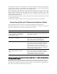
Chapter 5 Troubleshooting and Diagnostics 5.2 Installation and Operation Manual Monitoring Performance Displaying SHDSL Performance ASMi-52CQ has capabilities for collection of SHDSL parameters performance diagnostics. The statistics are accessed via the RADview SNMP management parameters tool. The parameters are listed in Table 5-1. Table 5-1.
Installation and Operation Manual Chapter 5 Troubleshooting and Diagnostics Table 5-2. E1/T1 Performance Monitoring Parameters Display Description BPV last minute Number of BPV events detected in the last minute BPV worst minute Number of BPV events detected in the worst minute Sync/Sync Loss (E1/T1 status) Framed operation – loss of frame alignment, unframed operation – loss of signal CRC error events Number of CRC error events recorded since the last time the register was cleared.
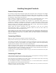
Chapter 5 Troubleshooting and Diagnostics 5.3 Installation and Operation Manual Handling Alarms ASMi-52CQ alarm buffer stores system alarm records, which can be viewed on either an ASCII terminal (see below) or an SNMP management tool. When one or more alarm records appear in the buffer, the front panel ALM LED lights up. After the alarm is cleared, the ALM LED turns off.
Installation and Operation Manual Chapter 5 Troubleshooting and Diagnostics MODEM ALARM STATUS MODEM NAME : ASMi-52CQ DEFINE MODEM PORT NUMBER : 1 SELECT MODEM : MODEM 1 LOCAL LINE DISCONNECT : OFF REMOTE MODEM POWER OFF : OFF : OFF TRANSMIT CARRIER : OFF NVRAM FAILED RECEIVE CARRIER : OFF PROP PROTOCOL FAILED LLB BY DTE : OFF SOFTWARE DWL IN PROCESS RLB BY DTE : OFF INCOMPATIBLE CONNECTORS SYNC LOSS A : ON SYNC LOSS B CRC6 ERR EXC A : OFF OFF CONFIGURATION MISMATCH : OFF PHASOR OVERFLOW EXC ILLEGAL EXTER
Chapter 5 Troubleshooting and Diagnostics Installation and Operation Manual MODEM ALARM STATUS MODEM NAME : ASMi-52CQ DEFINE MODEM PORT NUMBER : 1 SELECT MODEM : MODEM 1 LOCAL LOOP ATTN A : OFF LOOP ATTN B SNR MARGIN A : OFF SNR MARGIN B LOSW FAIL A : OFF LOSW FAIL B INCOMPATIBLE DATA RATE : OFF INCOMPATIBLE PSD WIRE NOT COMPATIBLE : OFF : : : : OFF OFF OFF OFF Figure 5-3. Modem Alarm Status (SHDSL Alarms) Table 5-5 lists the ASMi-52CQ alarms in alphabetical order.
Installation and Operation Manual Chapter 5 Troubleshooting and Diagnostics Terminal Message Alarm Type Description Severity E1/T1 FRAME SLIP EXC DTE E1/T1 frame slips exceed the threshold E1/T1 EXCESIVE BPV DTE Bipolar violations rate exceeds 1×10 during the last 1000 seconds E1 CRC-4 EXC DTE CRC-4 errors exceed the threshold Minor -6 Major Major -3 E1/T1 EXCESIVE ERR RATIO DTE The bit error rate of the link exceeds 10 E1/T1 AIS OCCURED DTE AIS is detected at the E1/T1 port Major E
Chapter 5 Troubleshooting and Diagnostics 5.4 Installation and Operation Manual Troubleshooting Using LEDs You may locate and correct some failures by using the front panel LEDs (see Table 5-3). Table 5-4 lists the alarm buffer messages, seen on the ASCII terminal or the RADview SNMP management tool. Table 5-3.
Installation and Operation Manual 5.5 Chapter 5 Troubleshooting and Diagnostics Testing ASMi-52CQ The user-controlled test functions of ASMi-52CQ consist of the loopback tests, BER test and LEDs tests. The purpose of these tests is to determine the source of a break in the data flow. The Modem Diagnostic screen enables you to configure loopback connections, and initiate LEDs test. Initiating Loopback and LED Tests ³ To initiate loopback or LED tests: 1. From the Main menu, select Modem Diagnostics. 2.
Chapter 5 Troubleshooting and Diagnostics Installation and Operation Manual Table 5-5.
Installation and Operation Manual Chapter 5 Troubleshooting and Diagnostics Setting Loopback Tests ASMi-52CQ supports the local analog loopback, remote digital loopbacks as per ITU V.54. V.54 loopback connections are set from the RADview SNMP management tool or from an ASCII terminal (see Section 5.2) The TST LED on the front panel of the local unit lights up and remains lit while the loopback is being run.
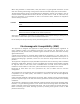
Chapter 5 Troubleshooting and Diagnostics Installation and Operation Manual Local ASMi-52CQ Remote ASMi-52 Data Clock Transmit Receive Glue Logic Local DTE Line Interface Glue Logic Line Interface Remote DTE Data Clock Receive Transmit Figure 5-6. Remote Digital Loopback (RLB) Running the Bit Error Rate Test (BERT) It is possible to generate BERT+RLB or BERT tests (from both CO and CPE) in E1 and DTE Serial units. These tests can be set only if there is a connection to the FE unit.
Installation and Operation Manual Chapter 5 Troubleshooting and Diagnostics The following are the BERT test patterns that can be selected: • 2E15-1 • Mark • Space • Alternate BERT has a possible Single Error injection only.
Chapter 5 Troubleshooting and Diagnostics Installation and Operation Manual Answer: The LRS-24 manages ASMi-52CD and ASMi-52CQ cards like any other Imode modem. This means that there are no separate IP addresses for each card in the LRS, and the SNMP agent your NMS communicates with is the CM-2, not the modem itself. 5.7 Technical Support Technical support for this product can be obtained from the local distributor from whom it was purchased.
Appendix A Pinouts A.1 LRSI-F-18 and LRSI-F-19 Connections DCE Connector Pinout for LRSI-F-18 and LRSI-F-19 The DCE interface of the LRSI-F-18 and LRSI-F-19 modules terminates in a 68-pin SCSI connector (see Table A-1 for connector pinout). Table A-1. Pin Assignment of the DCE Connector for LRSI-F-18 and LRSI-F-19 Type Data Ground Connector Control RS-530 X.
Appendix A Pinouts Note Installation and Operation Manual There are four SCSI pins that are not assigned. Line Connector Pinout for LRSI-F-18 The line interface of the LRSI-F-18 module terminates in an RJ-11 line connector, (see Table A-2 for the connector pinout). Table A-2. Pin Assignment of the RJ-11 Line Connector for LRSI-F-18 Pins ID Function Direction 1, 2,3 – Not connected – 4, 5 LINE Bidirectional line Input/Output 6 – Not connected – A.
Installation and Operation Manual A.3 Appendix A Pinouts LRSI-F-21 and LRSI-F-29 Connections DCE Connector Pinout for LRSI-F-21 and LRSI-F-29 The DCE interface of the LRSI-F-21 and LRSI-F-29 terminate in a DB-25 female connector (see Table A-5 for connector pinout). Table A-5.
Appendix A Pinouts Installation and Operation Manual CH1-RX CH1-TX CH2-RX CH2-TX CH3-RX CH3-TX CH4-RX CH4-TX Figure A-1. CBL-LRSI21/DB25/UB Cable Table A-7.
Appendix B Parameter List This chapter lists: • Command options to manage the ASMi-52CQ modem using an ASCII terminal • Parameters with their values and explanations. B.1 ³ Configuring Advanced Modem Parameters To configure advanced modem parameters: 1. From the Main menu, select Modem Operation. 2. Select the ASMi-52CQ slot. The Modem Advanced Setup menu shown in Figure B-1 appears.
Appendix B Parameter List Installation and Operation Manual Table B-1.
Installation and Operation Manual B.2 Appendix B Parameter List Configure Transmission Parameters The Modem Setup menu allows you to configure transmission parameters of ASMi-52CQ, including line and DTE values. ³ To configure the transmission parameters: 1. From the Main menu, select Modem Parameters. 2. Select the ASMi-52CQ slot. The Modem Setup menu appears (see Figure B-2). The Modem Setup menu enables you to set the transmission parameters of the local and remote modems. 3.
Appendix B Parameter List Installation and Operation Manual MODEM SETUP ASMi-52CQ MODEM NAME: DEFINE MODEM PORT NUMBER MODEM STATUS SELECT MODEM SYNC/ASYNC : N/A NO.
Installation and Operation Manual Appendix B Parameter List MODEM NAME: ASMi-52CQ DEFINE MODEM PORT NUMBER: 1 MODEM STATUS : MASTER PERMANENT SELECT MODEM : MODEM 1 LOCAL POWER BACKOFF : DISABLE SNEXT MARGIN : DISABLE MARGIN CURRENT MARGIN : DISABLE MARGIN ASYM PSD : SYMMETRIC LINE PROB : FIXED PORT CLK SOURCE : MASTER CLOCK CONFIGURED WIRE : 2W TRANSMISSION MODE : ANNEX B ATTENUATION THRESHOLD : 0 SNR MARGIN THRESHOLD: 0 MUX MODE : N/A LOW SPEED OPERATION : N/A Figure B-4.
Appendix B Parameter List Installation and Operation Manual Table B-3. Modem Setup: E1 Parameters Parameter Type Use Value Indication MODEM NAME Read Identifies the modem type which status is being viewed or modified ASMi-52CQ Master ASMi-52CQ ASMi-52 Standalone ASMi-52 modem MODEM STATUS Read Displays the modem configuration control status MASTER PERMANENT N/A FRAME MODE Write Selects the framing mode Unframed Stream of bits at 2.
Installation and Operation Manual Appendix B Parameter List Parameter Type Use Value Indication TS Write Assigns each timeslot to carry data DATA TS0 may be looped or transparent: Looped: TS0 is sent back to the E1 interface, when operating opposite remote units with a serial data interface. Transparent: TS0 is transmitted to the remote modem. NOT_CONNECT With G732S transparent framing, TS0 is always transparent and TS16 is always connected. When operating opposite an ASMi-52CQ with V.
Appendix B Parameter List Installation and Operation Manual Parameter Type Use Value Indication RECEIVE GAIN Write Sensitivity of the receive equalizer Long -36 dB Short 15 dB DSU DSU interface CSU CSU interface Length of a cable in feet between the T1 port connector and the network access point 0 feet 0 to 133 feet 133 feet 133 to 266 feet 266 feet 266 to 399 feet 399 feet 399 to 533 feet Relative T1 output transmit level 7.5 dB Attenuation of 7.
Installation and Operation Manual Appendix B Parameter List Table B-5.
Appendix B Parameter List Installation and Operation Manual Parameter Type Use Value Indication ASYM PSD Write Defines the amount of power applied to the information signal in order to achieve a satisfactory level of signal strength at the receiving end of the circuit Symmetric Supported in both Annex A and Annex B modes Asymmetric • Annex A at 768 kbps LINE PROB Write PORT CLK SOURCE Write • Annex B at 2048 kbps Indicates whether the modem should perform a line probing in order to find t
Installation and Operation Manual B.3 ³ Appendix B Parameter List Displaying Modem Status To display modem status: 1. From the Main menu, select Modem Status. 2. Select the ASMi-52CQ slot. The Modem Status screen appears (see Figure B-5). The Modem Status screen provides information on the system interfaces and front panel LED status. Table B-6 explains the parameters on this screen. 3.
Appendix B Parameter List Installation and Operation Manual Table B-6.
Installation and Operation Manual Parameter Type Use HW VERSION Read Displays current hardware version HW PANEL VERSION Read Displays current LRSI panel hardware version LED STATUS Read Displays status of front panel LEDs Appendix B Parameter List Value Indication ON, OFF (for interpretation of the LED states, see Chapter 2 MODEM NAME: ASMi-52CQ DEFINE MODEM PORT NUMBER: 1 SELECT MODEM : MODEM 1 LOCAL WIRE MODE : 2W PS1 TYPE SHDSL MODE : STU-C PS2 TYPE BERT PATTERN : N/A FRAMER TYPE : SLOT
Appendix B Parameter List Installation and Operation Manual Parameter Type Use Value PS1 TYPE Read Type of power supply 1 (remote standalone only) AC, DC PS2 TYPE Read Type of power supply 2 (remote standalone only) AC, DC SHDSL MODE Read Modem location STU-C Central WIRE MODE Read Line interface type 2W 2 wires BOX TYPE Read Type of remote unit enclosure PLASTIC SHDSL framer type N*64 FRAMER TYPE Read Indication METAL E1 SLOTTED (E1 only) T1 SLOTTED (T1 only) ACTUAL ANNEX
Installation and Operation Manual Appendix B Parameter List Parameter Type Use CURR NOISE MARGIN A Read 0-20 dB CURR NOISE MARGIN B Read 0-127 dB MUX TYPE B.4 ³ Value E1, E1 + LAN, E1 + IR Remote Not Mux Local Indication Displaying the Modem Log File To display the modem log file: 1. In the Modem Setup menu, select Modem Log File. 2. Select the ASMi-52CQ slot. A typical Modem Log File screen is shown in Figure B-7.
Appendix B Parameter List B-16 Displaying the Modem Log File Installation and Operation Manual ASMi-52CQ Ver. 2.
Appendix C LRSI-F-27 Module C.1 Overview The ASMi-52CQ-Ethernet card includes four SHDSL independent modems for four 10/100BaseT Ethernet ports. The ASMi-52CQ-Ethernet card supports full or half duplex mode, autonegotiation, auto MDI-X and filtering at each of the 10/100BaseT Ethernet port. The ASMi-52CQ-Ethernet card uses the LRSI-F-27 interface that has an Ethernet Port Bridge and an SHDSL line interface for each modem.
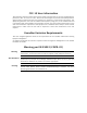
Appendix C LRSI-F-27 Module Installation and Operation Manual Application Figure C-1 shows an integrated high performance Ethernet bridging in modems with LRSI-F-27. The ASMi-52CQ-Ethernet card provides simple and cost-effective interconnection between 10/100BaseT LANs. Figure C-1. Central Site Application with SNMP Management Application Features C-2 • High performance Ethernet/Fast Ethernet bridge module • Compatible with IEEE 802.3, 802.1P 802.1Q, 802.1D (relevant parts), 802.3x, 02.
Installation and Operation Manual Appendix C LRSI-F-27 Module • Automatic MDIX support • Supports transparent VLAN forwarding • Packet length of up to 1536 bytes • Fault propagation of line interface error conditions to Ethernet port (optional feature) • When filtering is enabled, there are two QoS levels via two priority queues to handle priority, which is determined in the following order: If the packet received is an Ethernet tagged frame, product marks the packet according to the tag prior
Appendix C LRSI-F-27 Module Installation and Operation Manual LRSI-F-27 Front Panels Options Figure C-2 shows the two LRSI-F-27 front panel options, LRSI-F-27 and LRSI-B-27 modules. Figure C-2. LRSI-F-27 Module C-4 Overview ASMi-52CQ Ver. 2.
Installation and Operation Manual C.2 Bridge Ethernet interface Appendix C LRSI-F-27 Module Technical Specifications LAN Table 2048 MAC addresses with 5-minute automatic aging Aging 5 minute, automatic Buffer size 120 frames (Frame size 64 bytes) Packet Length Up to 1536 bytes Standard IEEE 802.3/Ethernet V.2, 802.1P, 802.1Q, 802.1D (relevant parts), 802.3x, 802.
Appendix C LRSI-F-27 Module Installation and Operation Manual Indicators LRSI-F-27 features two front-panel LEDs that indicate the link integrity and the Ethernet interface status. The function of each LED is described in Table C-2. Table C-2. LRSI-F-27 LEDs Warning LED Color Location Indication LINK Green Connector ON – Ethernet is connected ACT Yellow Connector Blinking – Ethernet Rx/Tx activity LRSI-F-27 module operates with ASMi-52CQ-Ethernet card only.
Installation and Operation Manual Appendix C LRSI-F-27 Module Table C-3.
Appendix C LRSI-F-27 Module Installation and Operation Manual MODEM SETUP ____________________________ MODEM NAME : ASMI-52CQ-ETH DEFINE MODEM PORT NUMBER : 1 MODEM STATUS : MASTER PERMANENT SELECT MODEM : MODEM 1 LOCAL SYNC/ASYNC : N/A CHARACTER LENGTH :N/A No.
24 Raoul Wallenberg Street, Tel Aviv 69719, Israel Tel: +972-3-6458181, Fax +972-3-6483331, +972-3-6498250 E-mail: erika_y@rad.com, Web site: http://www.rad.com Customer Response Form RAD Data Communications would like your help in improving its product documentation. Please complete and return this form by mail or by fax or send us an e-mail with your comments. Thank you for your assistance! Manual Name: ASMi-52CQ Ver. 2.
Error Report Type of error(s) or problem(s): Incompatibility with product Difficulty in understanding text Regulatory information (Safety, Compliance, Warnings, etc.) Difficulty in finding needed information Missing information Illogical flow of information Style (spelling, grammar, references, etc.) Appearance Other Please list the exact page numbers with the error(s), detail the errors you found (information missing, unclear or inadequately explained, etc.
Publication No. 695-213-07/08 International Headquarters 24 Raoul Wallenberg Street Tel Aviv 69719, Israel Tel. 972-3-6458181 Fax 972-3-6498250, 6474436 E-mail market@rad.com North America Headquarters 900 Corporate Drive Mahwah, NJ 07430, USA Tel. 201-5291100 Toll free 1-800-4447234 Fax 201-5295777 E-mail market@radusa.com www.rad.