
Specifications

ASMi-52CQ Ver. 2.12 2BSite Requirements and Prerequisites 2-1
Chapter 2
Installation and Operation
2.1 Introduction
This chapter provides installation and operation instructions for the ASMi-52CQ
card and the applicable Interface modules. The information presented in this
chapter supplements the general instructions for installation and operation of the
LRS-24F or LRS-24B chassis.
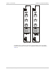
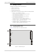
After installing the ASMi-52CQ modem and interface module and powering up the
chassis, the front panel LEDs should assume the states as shown in
Chapter 3
. In
case of a problem, refer to
Chapter 6
. For system configuration, refer to
Chapter 4
.
The operator or the user should not perform internal settings, adjustment,
maintenance, and repairs; such operations should only be performed by a skilled
technician aware of the hazards involved.
Always observe standard safety precautions during the installation, operation,
and maintenance of this product.
The ASMi-52CQ module contains components sensitive to electrostatic discharge
(ESD). To prevent ESD damage, always hold modules by the sides and do not
touch the module components or connectors.
Before installing the product, review
Handling Energized Products
at the
beginning of the manual.
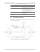
2.2 Site Requirements and Prerequisites
ASMi-52CQ cards are installed in a LRS-24 chassis. See the LRS-24 Installation
and Operation Manual for instructions on operating the LRS-24.
The ambient operating temperature of ASMi-52CQ should be 32° to 113°F
(0° to 45°C), at a relative humidity of up to 90%, non-condensing.
ASMi-51CQ modem cards installed in the LRS-24 hub require cooling. This is
provided by a fan tray installed under the LRS-24.
Warning
Caution
Note